• This Forum is for adults 18 years of age or over. By continuing to use this Forum you are confirming that you are 18 or older. No content shall be viewed by any person under 18 in California.

Dynamic Balance of Bullets

Have you weighed a sample of [unmodified] bullets from the same Lot to determine the overall weight range? Determining the total weight range of 20-30 bullets ought to give you a pretty good idea of how the 0.5 gr you removed compares to normal bullet weight variance within the Lot.

I've encountered total weight variance within Lots of 185 to 200 gr 30 cal bullets of as much as 0.3 to 0.4 gr. Obviously, the 0.5 gr weight you removed is highly localized as compared to normal weight variance within a Lot of bullets. Nonetheless, if the 0.5 gr weight you removed falls within the normal weight variance of that Lot of bullets, you might want to remove a little more for your preliminary testing and proof-of concept experiments.
 
Just speculating here, but I would guess that the real unbalance we'd find in regular bullets is probably due to jacket tolerances. However - those tolerances are crazy tight. In reality, the signal we are looking at tracking will be very small for normal (not intentionally damaged) bullets.

That's not to suggest that being able to measure this is without value - if nothing else, it can tell us more about different bullets in comparison to others, or to quantify the impact of defective jacket lots, for example. I'm not too optimistic that it will show up as something that we could sort a box of bullets with. But I could be wrong.
 
I ran a few tests today with a modified 230gr bullet. I took off 0.5gr with the edge of a file by removing a little copper from two places on the same side of the bullet jacket. Thinking this would be enough to give an increase in vibration magnitude over the standard bullet.

Initially I got readings of about double the magnitude over the unmodified bullet. Problem is that it is not reliably repeatable over the noise of the sensor when the machine is running. The alignment and pressure of the bearings on the bullet plays a big part in the readings obtained.

The software worked fine and allowed be to set up filters, etc, but the readings always came down to how I placed the bullet in between the bearings. Pushing the bearings in toward the centre of the bullet increased the vibration level and pulling them apart allowed the bullet to run much quieter.

There is no way I can use this device as it is now to sort bullets into lots of balanced and unbalanced (outliers) the readings I'm getting are not reliable enough. So its back to the drawing board for one last attempt using a much softer cradle. The bearings work well and dont damage the bullet but are difficult to place for reliable/repeatable use in testing.

Can any bullet maker reading this give me their expert opinion on if a 0.5gr reduction on one side of the bullet is a reasonable amount to use for testing. How much variance in weight do you guys consider allowable for manufacture? It would be nice to have a guesstimate on what weight an air bubble in a lead core might be for the 230gr bullets. If I have a worst case scenario then I can use maths to work out what magnitude forces are in play and get some idea of the suitability of the accelerometer.

Bullet markers like Sierra and Berger advertise a jacket tolerance of .0003 of an inch as the maximum allowable variance. see below

https://www.sierrabullets.com/resources/bullet-selection/index.cfm#matchking
http://www.bergerbullets.com/products/j4-precision-jackets/

Depending on the diameter of the bullet that variance will have a greater or smaller effect on the total .cg offset assuming that the core is solid lead and not contaminated with anything else.

Your modified bullet has a cg offset of .00036 of an inch assuming it was balanced to begin with and you didn't inadvertently balance it by chance. (.5/229.5*.154)

Of the 180 bergers bullets I tested on a static balance they had an avg offset of .0001137 inches. I think you removed enough material to create a worse case scenario but you could remove 1 grain to be certain your calibration bullet is unbalanced.

Good luck with your machine it looks pretty cool.
 
I wonder if using a preloaded spring to push one of the bearings would help even things out. But I'm concerned that even with filing the bullet you're having trouble finding the signal - I would expect realsitic defects to be more subtle. Most bullet boxes don't even vary by half a grain in my experience. Does the software have an FFT function? I wonder if there is any resonance in the fixture that's covering things up. The signal of interest ought to be at a predictable frequency.
All good points, software does have FFT function and yes I am looking for an imbalance to show up as a sine wave at around the frequency of the bullet rpm/Hz. I need to build a better cradle for testing, one that keeps the bearings aligned and allows greater movement (more flexible).
 
You might be best starting at the beginning and learning how bullets are made. Bearings MUST be inline and 90* to each other. otherwise you will induce imbalance from an elliptical hole that bullet rests in. Bearings themselves all have vibration unless you bought see $$$$ class , I would recommend ceramic they are reasonably priced and a whole bunch smoother. I would buy a gage pin that correctly fits bearing bore and grind ends square then check to see what it picks up. This should give a reference to check from. continue on
All good advice thanks! I have thought about ceramic bearings and will look into them and see if available in the OD/ID I need. Gauge pin is another thing I would like to have it would allow a calibration of sorts. Lastly your right about needing to keep the bearings aligned and also at the same distance apart when supporting the bullet. Need to design a new cradle that allows this.

Probably chasing unicorns with dynamic bullet balancing, but I will see what I can put together now that I realise it requires more engineering.
 
Bullet markers like Sierra and Berger advertise a jacket tolerance of .0003 of an inch as the maximum allowable variance. see below

https://www.sierrabullets.com/resources/bullet-selection/index.cfm#matchking
http://www.bergerbullets.com/products/j4-precision-jackets/

The only thing they are not telling ,is they only guarantee at specified datum point not the whole length of the jacket if my memory is serving correctly its ,200 on short range 6's and .300- .350 0n 30's I would need to look up prints but am not that motivated.....
 
Have you weighed a sample of [unmodified] bullets from the same Lot to determine the overall weight range? Determining the total weight range of 20-30 bullets ought to give you a pretty good idea of how the 0.5 gr you removed compares to normal bullet weight variance within the Lot.
I just weighed 100 Berger Hybrid 230gr bullets from a new box and ran it thru a spreadsheet to determine the range and a few other stats while I was at it. The bullets were weighed on my A&D FX120i which allowed me to weigh in grains down to two decimal places.

The spreadsheet results did not pick up a single outlier and not one bullet weighed under 230g! This sort of result is what made me think perhaps dynamic imbalance was the cause for the flyers. After trying different powders, primers, cases and barrel twist rates, not to mention different shooters, the consensus was that it was something to do with the bullet.

Max 230.38
Min 230.04
Median 230.16
Range 0.34
SD 0.073

Q1 230.1
Q3 230.22
IQR 0.12
Upper Bound 230.4
Lower Bound 229.92
 
Last edited:
Your modified bullet has a cg offset of .00036 of an inch assuming it was balanced to begin with and you didn't inadvertently balance it by chance. (.5/229.5*.154)

Of the 180 bergers bullets I tested on a static balance they had an avg offset of .0001137 inches. I think you removed enough material to create a worse case scenario but you could remove 1 grain to be certain your calibration bullet is unbalanced.

Good luck with your machine it looks pretty cool.
Titan, I will take 1 grain off in total and retest the bullet. I'm new to world of dynamic balance machines and what realistic expectations to have of the DynexHobby device and sensor.

I tried the suck it and see method and yes it looks the part but now I need to research the engineering and find out if its possible to do what I want. My background is electrical/electronic tech level, so now to look at data sheets and cradle design and dynamic balance equations.

I contacted DynexHobby and got a reply back straight away saying even for simple imbalance testing for outliers the 2 plane method is best. He also said he did not recommend the device for balancing bullets. Seems most people in discussion on this assume you want to balance the bullet under test, not simply test for imbalance.
 
A weight variance range for 100 bullets of 0.34 gr is pretty close to the amount you removed (0.5 gr). As I stated previously, the weight you removed is much more highly localized than would be expected for any of the outliers straight out of the box. Nonetheless, as a first step toward determining whether your setup is sensitive enough for your intended purpose, you may want to try a few bullets with more weight removed such that you can clearly identify the lower limit of detection.
 
I wish you well on this! I have spent many hours trying different techniques. Di section of a bullet on a mill can show that sometimes when the punch die pushes the bullet out it really disrupts the lead, and not always in a uniform manner. I always thought this could add some instability. I am in no way in your guys league to help much, but I can tell you what a Jaunke machine can tell you.

How much dust or imperfection is on the bullet jacket. Picks that up every time. I have spent many hours with that thing and all I can tell you is that is a waste of time. I talked with a very well known large scale bullet maker who placed a toothpick inside a bullet and could not pick out the spot with this machine. I have mine on loan right now to another really good shooter, Maybe man bun can figure it out.

Keep us posted if you can finally get this idea working. I think it has merit. Good luck.
 
Di section of a bullet on a mill can show that sometimes when the punch die pushes the bullet out it really disrupts the lead, and not always in a uniform manner.
The ejection pin on a point up die never touch's the lead, the jacket is closed down until pin knocks the formed bullet out. this is with jacketed hollow points.... any movement with core is when bullet is pointed up and ogive is formed pushing lead to a smaller diameter and forward creating a dome at the top of the core....
 
I am in the process of getting some parts together to make a high sensitivity pendulum suspension cradle, upon which I will use the same tiny pillow blocks to hold the bullet concentrically while it gets spun up to speed. This should isolate the vibration caused thru bullet unbalance if there is any for me to measure. I will get back to this thread when I have made some progress and have something more to report.
 
Please bear with me, I will get down to something pertinent to rifle shooting and this old thread.

I am primarily a long range rifle shooter, however for the past 6 years I have engaged part time in a study of 9mm accuracy. Best testing success has been with a TCM bolt action rifle converted to 9mm. I have a few good 5 shot 100 yard groups (0.75 inch) but little consistency. I began to wonder if bullet imbalance could be a factor.

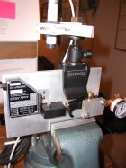
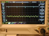
After experimenting with motor driven approaches to imbalance measurement, I moved on to a system that suspends and spins bullets using air. Ideas for the system came from Harold Vaughn’s book: “Rifle Accuracy Facts” but also from a 1944 US Patent by T. J. Dietz “Bullet Spinning Machine”. I use a laser diode distance measurement sensor aimed at the side of the spinning bullet. I also integrate a laser photoelectric sensor to simultaneously indicate the rotational position of the bullet and to measure RPM. Output from the sensors is displayed on an oscilloscope. Please refer to the included pictures.

I consider the system in its current configuration a successful proof of principle that could be applied to rifle bullets. The positive results so far are:

Stable spinning

Multiple surface measurements for each revolution

Rotational position for each measurement

Accurate indication of RPM.

Eccentric motion should coincide with the position of mass displacements. Current surprising result:

Displacement of the bullet surface is not synchronized with rotational position.

I have two possible theories. 1) Harmonic vibration of the test system. 2) Bullet vibration brought on by acoustic instability in the air flow around the bullet.

I hope others are interested in measuring bullet imbalance and will comment on this system. I am happy to answer questions and/or provide additional information.
P5140175.JPGHornady147polished5-18-20.JPG
 
I have two possible theories. 1) Harmonic vibration of the test system. 2) Bullet vibration brought on by acoustic instability in the air flow around the bullet.

I hope others are interested in measuring bullet imbalance and will comment on this system. I am happy to answer questions and/or provide additional information.

There is a large body of literature regarding spinning samples in NMR (nuclear magnetic resonance); the samples are liquids in glass tubes of very high precision (typically 5 mm OD at 10-30 Hz), or solid powders enclosed in ceramic rotors (usually 1.5-10 mm spun at 1-40 kHz). Spinning systems can be ordered from at least some of the vendors, but you'll probably have to make your own. Moving magnet of piezoelectric phonograph cartridges make very good sensors - they need less than a gram in contact with a moving body and produce relatively large signals, and they're inexpensive. I've been retired for a decade, so I no longer have access to scientific journals; you'll have to do your own searches (I'd suggest making friends with a librarian at a university). Good luck!
 
Just out of interest does anyone know if Berger or any other of the bullet manufacturers test the bullets for dynamic balance as part of their quality testing of their product?

Here is a link to a USA made test machine and if you scroll slightly down the page you will see a photo of a bullet undergoing balance testing.

http://www.balancemaster.com/

I tried this method of spinning bullets, (on two sets of bearings) and could not get it to work anywhere near well enough. The bullet boat tail and nose are both tapered and the bullet would move back and forth between the bearing supports.

The price of these machines is in the 10's of thousands of dollars!
See what dimensions are tracked for BERGER BULLETS here: https://bergerbullets.com/information/why-berger/
 
The center of gravity of any bullet will be offset, to a greater or lesser degree, from the centerline or geometric axis. When a bullet is fired, it is forced to rotate about its geometric axis while in the barrel. When it departs from the barrel it will shift to spinning about its principal axis passing though its center of gravity. This results in a deflection that causes the bullet to land on the target at a different spot than it would have if the center of gravity had been perfectly located on the geometric axis. The magnitude of offset varies from bullet to bullet, and the location of the offset varies depending on how it is oriented in the chamber before firing. This results in dispersion of bullet impacts, i.e., larger groups.

Bullets with less offset in their center of gravity (better bullets) are expected to produce tighter groups. One goal of bullet balance testing would be to select bullets with less offset. A number of methods for selecting better bullets have been suggested. The method that started this thread intends to spin bullets on their geometric centers and then measuring the resulting vibration. The method that I am currently investigating involves spinning bullets on their principal axis and measuring the surface runout.
 
See the pictures from my first post showing the bullet balance test system and oscilloscope output for one bullet. Looking at the test system, the component mounted upside down on the left is the distance measuring laser. If you look close, you will see the laser spot on the side of the bullet. The laser photoelectric sensor at the top of the picture views the bottom of the bullet. Close examination of the bottom of the bullet will reveal a small mark. This upper sensor detects the change in reflection produced by that mark as the bullet spins. The air is not running and the bullet is not spinning in this picture. I use a blow-off valve as the air shut-off. The black plastic Delrin block attached to the blow off nozzle houses and delivers air to the spin chamber. A second piece of cylindrical Delrin is bored to form the spin chamber holding the bullet and is pressed into the Delrin block. If you look close again you can see the top of this Delrin cylinder.

The second picture (somewhat out of focus) is of the oscilloscope screen with a bullet spinning in the test system. The tick marks on the upper trace indicate the line on the base of the bullet passing under the beam of the upper sensor. The lower trace is comprised of numerous dots representing individual measurements from the distance measuring laser sensor out to the surface of the spinning bullet.
 
In addition to cast off as described above, the case where the geometric center line of the bullet is not parallel to the principal axis of the mass (think of material missing from opposite sides at the front and back of the shank). This will cause the bullet to fly at an angle to the line of flight (precession), which will increase drag; the angle of repose will not be zero even at long distance from the muzzle. Placing the distance sensor away from the center of mass of the bullet will detect this motion, but will not distinguish between the the two cases. Using two sensors (one at the center of mass and one offset) would allow them to be distinguished; however, that's not really the point of the exercise as we really only care whether the bullet is "good" or "bad" so a single sensor offset from the center of mass will suffice.
 
Thank you all for the replies to my input, and also for the original post plus many contributions in this thread.

Ronemus provides a good comment on nature of mass offset in bullets. A second runout sensor would help identify a condition where the principle axis is not parallel to the geometric centerline. The sensor I am using to measure runout must view the bullet. The current spin chamber combined with the short length of the pistol bullets under test only provides one viewing location. The greater length of rifle bullets may provide a view of the both the nose and rear body extending outside a spin chamber.
 

Upgrades & Donations

This Forum's expenses are primarily paid by member contributions. You can upgrade your Forum membership in seconds. Gold and Silver members get unlimited FREE classifieds for one year. Gold members can upload custom avatars.


Click Upgrade Membership Button ABOVE to get Gold or Silver Status.

You can also donate any amount, large or small, with the button below. Include your Forum Name in the PayPal Notes field.


To DONATE by CHECK, or make a recurring donation, CLICK HERE to learn how.

Forum statistics

Threads
165,591
Messages
2,199,123
Members
79,004
Latest member
4590 Shooter
Back
Top