• This Forum is for adults 18 years of age or over. By continuing to use this Forum you are confirming that you are 18 or older. No content shall be viewed by any person under 18 in California.

CCI BR4 and 450 primer problems

Is the wall thinned when stamped?
What is the weight of your 450 primers?
Could a "Vendor" have swapped out 400's for 450's?
Flipping a flat at a time wouldn't take long to MAKE extra boxes of 450 primers :)
OK, here's my measurement results I've just completed :rolleyes::

I took a new primer, removed the anvil, cleaned the primer compound out for a Rem 9 1/2 and for a CCI-450.

The 9 1/2 overall height measured .1185". Measuring into the bottom of the cup from the top measured .0905. .1185-.0905=.028, which is pretty close to the chart's stated spec. The primer wall measured .016".

The CCI-450 measured .1125 in overall height. Measuring inside to the bottom of the cup measured .0865. .1125-.0865=.026. Again, that's pretty close to the chart's stated spec. The primer wall again measured .016".

The walls on the primers ARE NOT the same thickness as the bottom of the cups.

BTW: The Rem 9 1/2 cup weighed 3.5 grs and the CCI-450 cup weighed 2.52 grs; anvils weighed 1.18 and .84 grs respectively. I didn't think of weighing them before I started to see just how much the compound weighed.
 
Last edited:
Manufacturers have the right to change specs and temporarily deviate from them unless there is a MIL spec they claim to meet or their tolerances are part of the advertised product specs. In the case of primers I expect they will 1) meet SAAMI specs for overall dimensions and 2) consistently and safely go bang. Nothing else.

It is my understanding that that chart is not a product spec. Its measurements complied by an individual at a point in time. They can change.

Also, that is not an entirely accurate way to get cup thickness on such a small diameter tube. Even the narrow points of the caliper are not zero width and as such there will be some chord error on the inside. You probably need a CMM or interchangeable anvil micrometer with a fairly small pin as the anvil.
 
Also, that is not an entirely accurate way to get cup thickness on such a small diameter tube. Even the narrow points of the caliper are not zero width and as such there will be some chord error on the inside. You probably need a CMM or interchangeable anvil micrometer with a fairly small pin as the anvil.
You're right and that's why I use two different instruments that I have to take measurements: a caliper of course, and a horizontal dial indicator that measures in .0005 increments. :D
 
OK, here's my measurement results I've just completed :rolleyes::

I took a new primer, removed the anvil, cleaned the primer compound out for a Rem 9 1/2 and for a CCI-450.

The 9 1/2 overall height measured .1185". Measuring into the bottom of the cup from the top measured .0905. .1185-.0905=.028, which is pretty close to the chart's stated spec. The primer wall measured .016".

The CCI-450 measured .1125 in overall height. Measuring inside to the bottom of the cup measured .0865. .1125-.0865=.026. Again, that's pretty close to the chart's stated spec. The primer wall again measured .016".

The walls on the primers ARE NOT the same thickness as the bottom of the cups.

BTW: The Rem 9 1/2 cup weighed 3.5 grs and the CCI-450 cup weighed 2.52 grs; anvils weighed 1.18 and .84 grs respectively. I didn't think of weighing them before I started to see just how much the compound weighed.
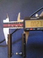
We were on the same page!!! I oiled the compound on a BR-2 to make the primer safe!!! Removed the anvil and cleaned the gunk out of the cup!! Grabbed my Mic attachments and measured 0.027" base with 0.015" walls!! See pic below!

The 0.025" thickness is the minimum thickness of Mil Specs!!! In other words, the military will not use primers less than 25 thou!!!!
 

Attachments

  • IMG_20240902_155626_burst_01.jpg
    IMG_20240902_155626_burst_01.jpg
    326 KB · Views: 38
You're right and that's why I use two different instruments that I have to take measurements: a caliper of course, and a horizontal dial indicator that measures in .0005 increments. :D
The issue was not accuracy!! The issue is the drawing is not right!!! Using my Mic attachments, I accurately measured the base thickness of 27 thou. I used the knife edges of the Mic and measured wall thickness of 15 thou!! Yes I have a secant to cord error on the inside knife edge, which makes the wall thickness SLIGHTLY less than 15 thou! It still proves the whole cup thickness is not a dimensional similarity as shown in the drawing!!!
 

Attachments

  • IMG_20240902_155626_burst_01.jpg
    IMG_20240902_155626_burst_01.jpg
    326 KB · Views: 12
Last edited:
Manufacturers have the right to change specs and temporarily deviate from them unless there is a MIL spec they claim to meet or their tolerances are part of the advertised product specs. In the case of primers I expect they will 1) meet SAAMI specs for overall dimensions and 2) consistently and safely go bang. Nothing else.

It is my understanding that that chart is not a product spec. Its measurements complied by an individual at a point in time. They can change.

Also, that is not an entirely accurate way to get cup thickness on such a small diameter tube. Even the narrow points of the caliper are not zero width and as such there will be some chord error on the inside. You probably need a CMM or interchangeable anvil micrometer with a fairly small pin as the anvil.
Yes, manufacturers can change specs at any time as long as the product is not under contract! But not with the government, military, or foreign country companies that use ISO standards!!! The drawing is incorrectly dimensions!! Fact from an engineer using mechanical drawing software (Autocadd 4 - Autocadd 2000) for 25 years!! Good old mechanical arm prior to computer aided drawings!!!

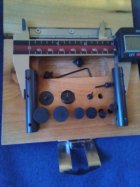
The base and wall thickness can be accurately measured using Mic attachments!! See pic below!!! Yes there is a slight error using the knife edges on small radii called secant to cord error!!! But accuracy was not the issue!!!

As an engineer, you have to learn to set tolerances!! I will say this, the reloader does not need to exceed one thousandth of an inch in measuring anything!!! I see some forum members with digital neck thickness C-Mics that read to one ten thousandth of an inch. The slightest taper and irregularities inside the neck are much greater than 0.0001". If your going to use measuring devices with that much accuracy, you had better be in a climate controlled environment with the sample(s) setting in that room for at lease a day!!!

And If your trying to show off, I have used air gauges that could measure 0.000005" of and inch in accuracy!! Or a lazer point locator that could measure 1000 yards, line of sight with a 1/16" error!! Lets quit this game of total accuracy beyond one thousandth of an inch!!!
 

Attachments

  • IMG_20240902_174756.jpg
    IMG_20240902_174756.jpg
    316 KB · Views: 31
The issue is the drawing is not right!!!
That's not the issue. The issue is pierced primers and how they got that way. It doesn't matter about the drawing. Maybe you could start a different thread that teaches anyone who cares how to measure stuff. Or draw stuff.
The issue is pierced primers and how they got that way. At least, I think that's the issue...
Beware The Guffey...
 
The issue is the FALSE assumption that the CAUSE of the blown primers was THIN CUPS.
"G'day all its been a long time since I had to buy primers as I have heaps but decided to grab some 450 and br4 and was surprised at them piercing so measured the cup thickness and it came up at 0.016" instead of the supposed 0.020" "

I think they pierced due to some other cause.
(Maybe the Guffey knows)
 
Yes telling the truth. The Master Rings that went out with the gauges were measured in the NASA Dimensional Lab.
Diameter, roundness, taper, and surface finish. These were used for QC checks of 3rd party laser hardened precision bores.

The only places gauges that accurate could be used was the Metrology lab, and the QC inspection room.

We used the HP Laser interferometer and Leica Laser tracker (before the rights were bought by Leica), and a Swedish 1ppm Coordinate Measuring Machine.
 
Last edited:
That's not the issue. The issue is pierced primers and how they got that way. It doesn't matter about the drawing. Maybe you could start a different thread that teaches anyone who cares how to measure stuff. Or draw stuff.
The issue is pierced primers and how they got that way. At least, I think that's the issue...
Beware The Guffey...
The issue was his measurements!! The drawing is wrong!! The 450 and BR-4 primers have a thickness in the base of 0.025in or more to meet mil spec!! He was measuring the thinners walls of the cup!! The thickness is no longer the issue!! The pierced primers are caused by improper seating, a sharp protrusion on the primer seating face or firing pin face, an over traveling firing pin, or lose primer pockets!!
 
If the ISSUE was his measurements blaming thin cups then the piercing would have disappeared once "WE" straightened him out on his measurement errors.
I do agree that the drawing has been misinterpreted.
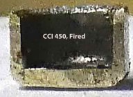
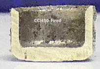
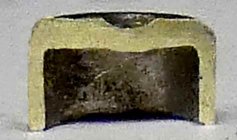
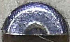
I don't think I need to measure the (fired) primers in my pics to show this.
Drawings, mil specs, assumptions of CCI450 dimensions only confused the ISSUE.

I still say the OP needs to look elsewhere for the CAUSE of the pierced primers.

The NEXT time this old primer chart comes up we will have forgotten every thing said here.
 
Last edited:
You left
Yes telling the truth. The Master Rings that went out with the gauges were measured in the NASA Dimensional Lab.
Diameter, roundness, taper, and surface finish.

The only places gauges that accurate could be used was the Metrology lab, and the QC inspection room.

We used the HP Laser interferometer and Leica Laser tracker (before the rights were bought by Leica), and a Swedish 1ppm Coordinate Measuring Machine.
Interesting!!! The air gauge heads came with two masters because of concentricity. These gauges were used after gun reaming hydraulic valve body bore(s) and honing the spool bore(s). Tolerances were 0.00001 concentricity (roundness) on each land and 0.000015 taper!!! You don't want hot, high pressure hydraulics oil leaking past the lands or spool!!! Honed cast iron bore with precision ground and honed chrome plating on a steel spool!! I sharpened the carbide gun reamers heads with a diamond cup wheel when I was a toolmaker class B while working for that company on 2nd shift while attending college for my Engineering Degree during the day!!!
 
Last edited:

Upgrades & Donations

This Forum's expenses are primarily paid by member contributions. You can upgrade your Forum membership in seconds. Gold and Silver members get unlimited FREE classifieds for one year. Gold members can upload custom avatars.


Click Upgrade Membership Button ABOVE to get Gold or Silver Status.

You can also donate any amount, large or small, with the button below. Include your Forum Name in the PayPal Notes field.


To DONATE by CHECK, or make a recurring donation, CLICK HERE to learn how.

Forum statistics

Threads
166,289
Messages
2,216,088
Members
79,551
Latest member
PROJO GM
Back
Top