Here is a research paper on the topic of the abrasive nature of carbon fiber when sliding across metal.
Handy link to article
Finite element modeling of indentation and adhesive wear in sliding of carbon fiber reinforced thermoplastic polymer against metallic counterpart
Israr Ud Din1,4*, Stéphane Panier1, Pei Hao1, Gérald Franz1, Jayashree Bijwe2, Li Hui31. Laboratoire des Technologies Innovantes, LTI-EA 3899, Université de Picardie Jules Verne, Amiens, 80025, France2.
ABSTRACT
In this work, adhesive wear in uni-directional (UD) reinforced carbon thermoplasticPolyetherimide (PEI) composite laminate caused by the sliding of a metallic counterpart isanalyzed. The study is based on the finite element method (FEM) in various in-plane directionsof sliding relative to fibers. The damage and failure mechanisms induced by the adhesive wearare predicted with 3D Hashin's theory and Puck's theory. These failure theories were implemented in ABAQUS via UMAT in implicit environment. The damage mechanisms predicted by the FEM model showed a better correspondence with the observed damage modes in the wear experiments of fiber reinforced polymers (FRPs). Furthermore, specific failure exposure factors were also compared with the specific wear rates determined experimentally in a qualitative manner.
Keywords: Adhesive wear, 3D Puck’s theory, Finite element modeling, Wear damage mechanisms.
1. Introduction
Fiber reinforced polymers (FRPs), specifically thermoplastics (PEEK, PES, PEI, etc.) reinforcedby carbon fibers (CFs), are used in the elevated temperature applications in tribo-componentswhere harsh operating conditions prevail such as in aircrafts. Previous studies show that CFs inthe tribo-systems offer partial lubricity in addition to higher specific strength, thermal conductivity, resistance to fatigue and damage, etc. [1, 2]. Such material combinations provideother advantages including recyclability in contrary to thermoset polymers as epoxy andunlimited shelf life [1]. It is important to study numerically the damage induced by the contact of two counterparts and the subsequent wear in FRPs. However, this numerical analysis of wear process is a very complex task to accomplish. Different types of fibers, their properties and fiber volume ratio make the numerical analysis of this process further difficult. Wieleba [3] describedthat the dominant wear process during the rubbing of fibrous composites is the adhesion. But depending on the type of fibers and friction conditions, other wear mechanisms may also been countered. Fundamental factors that influence the wear of fibrous composite materials includefiber type, fiber volume ratio in the composite, and the properties of the fiber/matrix interface. This study focuses on the UD based FRPs composite laminates under in-plane wear conditions.
Wear phenomenon in FRPs has been studied experimentally and literature is available for different modes of wear including abrasive wear and adhesive wear [1, 4, 5]. Cirino et al. [5]investigated the dry abrasive-dominant wear in UD composite in which the composite was worn in three principal directions. These three directions were designated as N (Normal), P (Parallel)and AP (Anti-Parallel) with respect to the fiber orientation as shown in Fig.1. P and AP wear directions are in-plane while wear in N-direction is out-of-plane and is not considered in this study.
View attachment 1586524
Fig. 1: Three principal sliding directions with respect to fiber, (a) Parallel (P), (b) Anti-Parallel (AP), (c) Normal (N)[6]
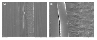
The damage mechanisms encountered in the abrasive and adhesive types of wear were studiedusing scanning electron microscopy (SEM) in each direction of sliding in the experiments [1, 2,7, 8]. In case of wear in direction P, a typical SEM micrograph can be seen in Fig. 2 [7]. Thisfigure shows different failure mechanisms during the wear process in FRPs composite. Thesecomprise fiber/matrix de-bonding, fiber bending, fiber cracking and matrix shear features. It isnoticeable in Fig. 2-a that the polished surface remained in its undamaged state away from the groove scratched by the diamond tip indenter. At higher magnification (see Fig. 2-b), a fibercrack transferring from one fiber to the next is noticeable. In addition, the formation of shear features can also be seen.
View attachment 1586525
Fig. 2: (a) SEM micrograph of P-direction composite surface scratched by a diamond tip indenter, (b) an enlarged view [7]
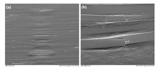
Similarly, Fig. 3 depicts the damage mechanisms when a FRPs composite is scratched by adiamond tip indenter in AP-direction. Due to the compressive and frictional loads, fiber bendingtakes place in the depth direction (out-of-plane bending) and also in the sliding direction (inplane bending). Both in-plane and out-of-plane bending ultimately contribute to fiber fracture inthe central region of the groove as well as in the transition between the groove and theundamaged area. The damage mechanisms are similar to the P-direction scratch including fiber/matrix de-bonding, shear features of the matrix material between the broken fibers, fibercracking and their removal from the fiber beds. Friedrich et al. [9] emphasized that if the diamond tip indenter is replaced with a small steel ball, the characteristic wear and damagemechanisms are very similar but these are not seen clearly as in case of the damage mechanisms produced by the diamond indenter.
View attachment 1586526
Fig. 3: (a) SEM micrograph of AP-direction composite surface scratched by a diamond tip, (b) a magnified view ofthe groove [7]
Friedrich et al. [7] explained that wear process takes place in a sequence of damage mechanismsand these were termed as wear cycles. Accordingly, the wear cycle initiates from the matrix wearand fiber sliding wear. Fiber sliding wear is also known as fiber thinning in the literature. These are followed by fiber cracking and fiber/matrix de-bonding at the interface. When the wear process reaches the steady state then a so-called compacted wear debris layer (CWDL) coversthe surface which is composed of pulverized fibers and matrix material. During the wear process,this layer is continuously formed and removed by the surfaces sliding against each other. The preceding studies were limited to only three directions comprising P, AP and N. Sharma et al. [2,8] carried out experimental studies in various fiber directions. UD carbon reinforced thermoplastics (PEI) with 80% by volume were tested at range of angles as 0°, 30°, 45°, 60° and 90° during abrasive wear [8] and in dry-adhesive wear [2]. The increase in the coefficient of friction (µ) was reported as the fiber angle with respect to the sliding direction was increased. In addition, very low specific wear rate 30 ( , volume removed per unit of wo K unit mm / : rk require N d = . ) m was determined for the sliding in the fiber direction (P-direction). On the other hand, the specificwear rate in AP-direction (90°) in the experiments was computed as four times higher than the P direction (0°). Ovaert [10] reported similar results by conducting wear experiments on fiberreinforced thermoset epoxy matrix. Sharma et al. concluded that sliding orthogonal to the fiber(AP-direction) leads to higher wear. In addition, they highlighted that in AP-direction, FRPs aremore vulnerable to de-bonding, peel-off the plies and the pulverization of fibers as compared to the P-direction sliding.


