• This Forum is for adults 18 years of age or over. By continuing to use this Forum you are confirming that you are 18 or older. No content shall be viewed by any person under 18 in California.

Bolt action pistol build

A while back somebody posted a pic of a benchrest stock for an Anschutz pistol and I thought it looked pretty cool and that I should have one. However an Anschutz will never be in my budget . I do have tools and a good imagination so well see what I come up with.
The parameters are
dual locking lugs
left bolt
left port
right hand eject
walnut stock
3 lever trigger
That ought to keep me busy for a while
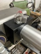
Normally I would make the receivers first but in this case since I have to make the triggers I made them first. It's an oddball configuration the sear is actually in front of the bolt lugs on the firing pin body itself. It works like a rem 3 lever trigger but it's backwards. I made a prototype out of aluminum to get the parts layout and hole locations. IMG_0351.jpg

Once I was sure it would work I milled a block of aluminum big enough to make two triggers . I have a piece of aluminum I put in the mill vise and make a skim cut on the top just to true it up then I glue the trigger housing to that, mill one side flip it over and mill the other side . Then drill and ream all the holes
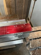
IMG_0353 (1).jpg

Once that's done cut out the middle and drill and tap the holes for the adjustment screws, sear engagement, overtravel and pull weight. I made a little ledge for the cover to sit on which is attached with 4 #2-56 flat head screws. For the internals I cut out some 5/32 O1 steel, glued two pieces together with the aluminum pattern glued to that and milled them out
IMG_0360.jpg
Here they are all together. The sear on the top will get trimmed off and the trigger will get final finished once it's in a stock and has a trigger guardIMG_0387.jpg
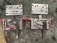
The last part to make was the brass piece for the end of the pull weight spring , keeps the spring straight and lined up with the hole. All the parts need the final polish. Once there installed I'll get everything cleaned upIMG_0386.jpg
 
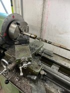
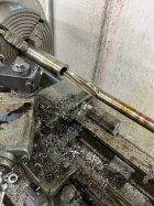
After the triggers I started on the receivers. 4140 drilled and reamed to to 11/16IMG_0398.jpgIMG_0399.jpg
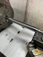
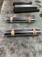
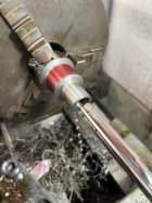
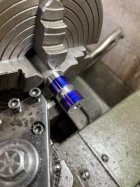
A grueling long process with progressively larger bits to allow chip clearance for the smaller ones till it gets to 5/8 all the way through then two reaming operations finishing up at 11/16 . 11/16 is the hole size for threading 3/4-16 which is the barrel tenon size . After boring and a cleanup with a flap wheel there turned between centers and polished up . Finished diameter is 1.075IMG_0400.jpg
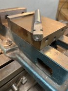
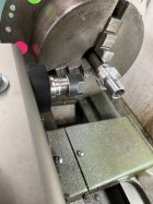
next their threaded for a tenon length of 7/8 inchIMG_0401.jpg
Once I get that far there glued (jb weld) into a piece of 1x1 aluminum angle. The angle gives me a reference to make a few more cuts before it's removed. The scope base holes are made using the angle against the solid jaw of the milling vise and the scope base becomes the vertical reference for the cuts on the bottomIMG_0388.jpg
stay tuned for tomorrows updates
 
Cutting out the receivers is a time consuming process. Lots of measuring and tooling changes but in the end I have two receivers cut out with only one screw up . My loading ports wont match, the one I screwed up will be a lot easier to load though. I may enlarge the smaller one before I'm all done.
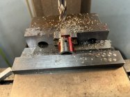
First thing is to drill and tap the holes for the scope base. IMG_0389.jpg
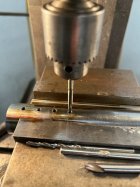
Next up is the raceway for the bolt lugs , the top is 7/16 the bottom is 3/8 more or less. I started with a 1/4 inch end mill then a 5/16 then a 3/8 and then finished the top with a 7/16. normally an end mill cuts a wider slot than its diameter but it really doesn't matter in this case I just make the next part fit the slot. I was pretty happy with how they came out . Nice finish and only 2 and a half thou over 7/16.IMG_0405.jpg
IMG_0393.jpg
Cutting the loading port next with a 1/4 inch ball mill. pretty simple just drill through and go around in a rectangle . there isn't anything really critical in most of the cuts ,most of the time I'm cutting to a scribed line and within a few thou is close enough.
time for a new end mill that one is really dullIMG_0396.jpg
The ejection port is next up pretty simple just a short 3/8 slotIMG_0408.jpg

I made it pretty small hopefully it works.
 
The slot for the bolt release is the last operation on the receivers for now . It's a 5/32 slot with two steps in it and 3/4 long, rough in with 1/8 end mill and finish with a 5/32IMG_0409.jpg The bolt lugs are the hardest part to make there is a lot of cuts to make and their pretty hard plus the helix for the cocking cams. First it's just a turning and boring operation
IMG_0421.jpg
then drill two holes 90 degrees and .250 apart which requires milling part of the extra material away.
IMG_0423.jpg
The part is glued to a sacrificial mandrel and a locating pin is used to put it back on for more carving on itIMG_0428.jpg
the holes are the ends of the cocking ramps . I milled a flat spot for the two lugs and that indexes it in the millIMG_0426.jpg
Lots of measuring and figuring then cut the top lug .440 wide
 
check the fit ,rotate it 180 and cut the other lug .375IMG_0425.jpg
IMG_0427.jpg
After the lugs are cut i milled a bunch of extra material away because for the next operation it goes back on the mandrel and the area between the lugs is cleaned upIMG_0437.jpg
This was done with the milling head for the lathe .120 carbide ball end mill. I probably spent 15 min sanding out the tool marks on both sides looks a lot worse than it is.IMG_0442.jpg
I shimmed up the milling head and set the compound to 36 degrees and connected the two holes for the cocking ramps. should have .250 pin fall. The lugs got the final trim and the off side lug got .050 removed from the front for running clearance. I guess next I'll start on the bolts.
 
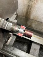
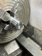
The bolts are actually bolts 3/4 inch grade 5 bolts. I've used grade 8 before but that's just too hard to work with. so I cut the heads and threads off with the band saw and turned these so they would just go into the receivers ,by the time their finished and polished up they'll be just rightIMG_0402.jpg
I squared up one end and cut the recess for the case head . .278 dia and .030 deep
IMG_0410 (1).jpg

The first one of these I did I made the extractors and the spring then I got some savage springs and used those and made the extractors now I'm using savage extractors and springs , sure is a lot faster and easier. One of the critical cuts is for the extractor spring . I had to make special cutters for the slot but their done nowIMG_0443.jpg

Next up is the flat on the bottom of the bolt at the front where the loading ramp goes
IMG_0446.jpg
And then the extractor cuts. I used to cut these with a 1/16 inch end mill then I discovered slotting saws that's a lot faster
IMG_0448.jpg

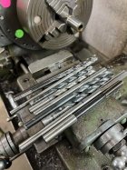
next up is drilling the bolts for the firing pin. their 5/16 at the bolt nose end for an inch and then 25/64 the rest of the way, all total 4.5 inches deep. Not as bad as drilling out a receiver thoughIMG_0445.jpg
That's the collection of drills and reamers for that job.
 
Loving it.

This is actually hard for me to watch, as I've wanted to do scratch builds for as long as I've been tinkering with guns, but it's totally illegal in Canada.
You have to get a manufacturer's license.
 

Upgrades & Donations

This Forum's expenses are primarily paid by member contributions. You can upgrade your Forum membership in seconds. Gold and Silver members get unlimited FREE classifieds for one year. Gold members can upload custom avatars.


Click Upgrade Membership Button ABOVE to get Gold or Silver Status.

You can also donate any amount, large or small, with the button below. Include your Forum Name in the PayPal Notes field.


To DONATE by CHECK, or make a recurring donation, CLICK HERE to learn how.

Forum statistics

Threads
164,777
Messages
2,184,127
Members
78,507
Latest member
Rabbit hole
Back
Top