Thank you. And thanks to all on this thread who have contributed. It has been a fun project. I am willing to share my code/design for anyone interested, after all, that's what this tread is all about, sharing ideas. I did not post the code as it is over 500 lines and felt most would not be interested in it.Really nice build the coil design is innovative and the flame detector to gauge temperature a really nice and new addition for others to try, Well done

You are using an out of date browser. It may not display this or other websites correctly.
You should upgrade or use an alternative browser.
You should upgrade or use an alternative browser.
Induction brass annealer redux
- Thread starter Gina1
- Start date


Thanks for your response, I looking at using a proximity sensor to trigger the start, they are normally 12-24V. Since the sensor will be energised whilst the brass is present, I'm not sure if this will affect the timer as the sensor is not momentary.There really isn't any voltage associated with those (or the Stop or Gate) pins. It is just a continuity issue between pin 1 (common) and 2 (Start)...if they are connected (ie by a momentary switch or relay) it will trigger the Start event (or Stop(1 to 12) or Gate(1 to 11)).
A diagram should be on the side of the timer housing.
How are you thinking of triggering the Start?
I know that several people (at least) have used proximity sensors in their builds, so I will let them jump in with their solutions.Thanks for your response, I looking at using a proximity sensor to trigger the start, they are normally 12-24V. Since the sensor will be energised whilst the brass is present, I'm not sure if this will affect the timer as the sensor is not momentary.
But, if I had to guess, they probably used the proximity sensor to trigger a relay to provide the continuity trigger to start the timer, since the proximity sensors I have researched (briefly) have 3 inputs...2 power (+/-) and 1 load (output power to the relay).
As far as being continuously on, you can test the timer by connecting the 1 and 2 contacts...I suspect the timer will start and run through its cycle even with the connection closed (ie proximity sensor detects case in place while heating cycle starts, runs, and ends).
Altenately, you could have proximity sensor detect the passage of the case as it drops into position to get a momentary on for the timer.
Last edited:
I have built 4 Arduino based induction annealer with case feeder for myself and friends and automated 1 Annie Induction heater with case feed and auto start, by far the most reliable and easy setup case sensor I found is a 5V Laser sensor module with a Laser transmitter module.For the Arduino based I use the laser module to trigger a solid state relay (SSR) to start the ZVS Induction heater and for the Annie the laser starts a PTR4 Controller which is very similar to Sestos or any other 4CH relay timer, the only drawback is you will need 5V to power the laser, easily done using a DC-DC Buck Converter Step Down Module Power Supply
Can you please share the code and materials list/design?Finally finished my GinaErick Annealer. I went with an Arduino Uno controlled annealer, a 4x20 LCD for display and 5 buttons (two for adjusting time up or down, two for cycling up or down through the 10 program slots and one to pause or clear errors). The first revision of my program provided 10 program slots for saving case name and anneal time. If you changed the anneal time and then moved to a different program slot, the new time was saved to EEPROM memory. The second revision added the ability to anneal based on energy (joules) and saved the joule setting for each slot as well. The final revision used the first program slot, slot 0, for an AUTO mode which uses a flame sensor to detect when the case neck glows and ends the annealing. The “Glow” setting is adjustable from undetectable by my eyes to “melt the neck”. In the video you can see the neck just begin to glow before the case drops.
I used a break beam sensor to detect when a case is present and to begin annealing and a trap door to drop the case out when done. Used a double wound coil, 6.5 turns, inside diameter of 0.65 inches. This allowed for better visualization of the case neck by the flame sensor. I’m using a 36V 27.5A power supply. Annealing can be interrupted by pressing the middle button, amps over 27.5 or temp of the 1000 Watt ZVS board over 180F.
The LCD line one displays the case program number/name and the time/joule/glow setting for that program slot. Line two displays the voltage, max amps during annealing and temperature of the ZVS board. Line three displays the actual anneal time, actual glow reading and actual joules of energy for each anneal. Line four shows what state the annealer is in, Pause Mode, Waiting for Case, Annealing, High Temp or High Amp error.
I also created multiple base plate inserts to accommodate and center different cartridge base diameter sizes. Everything was purchased on Amazon except for some small wood screws that I picked up at Lowe’s. Total cost $304 US. I have thousands of various headstamp .223/5.56 brass and found some would anneal at under 2 seconds and some at more then 4 seconds. I did not want the tedious task of sorting the cases by headstamp, which lead to the flame sensor (Teyleten Robot 3.3V-5V IR Infrared Flame Sensor 4 Pin Infrared Detection Module Detecting Distance 80cm, 10 pack for $6.31). Now no matter what case I put into the annealer, it is annealed just long enough to start glowing (approximately 1000F).
Thank You,
Tiago
Last edited:
Just sharing ideas.Thank you........ after all, that's what this tread is all about, sharing ideas.....
I find your idea of using IR module to determine the right glowing of the neck very attractive - especially annealing mixed brass. I have already ordered a few modules. I'm using Fluxeon in my current build (fan cooling only) and f I'm planning to "separate" the sensor from the board due to lack of space. My box is very small and I do not have anything outside of the box.
Instead of memory slots, I'm using the level position of my motorized gate platform to store different caliber recipes.
Proximity sensor - I would like to implement one, for the simple reason to tell Arduino - "yes the brass is in place - it's OK to start annealing" (sometimes the brass does not land correctly - especially with a feeder). So, I'm thinking to use the conductivity of the brass to make a contact closure utilizing very fine copper strands .
A proximity sensor using fine copper wire sounds interesting. The biggest problem I see would be making it work with different size cases. I used Gikfun 940nm infrared emitter and IR deceiver diode for Arduino (20 pack on Amazon for $5.58)Just sharing ideas.
I find your idea of using IR module to determine the right glowing of the neck very attractive - especially annealing mixed brass. I have already ordered a few modules. I'm using Fluxeon in my current build (fan cooling only) and f I'm planning to "separate" the sensor from the board due to lack of space. My box is very small and I do not have anything outside of the box.
Instead of memory slots, I'm using the level position of my motorized gate platform to store different caliber recipes.
Proximity sensor - I would like to implement one, for the simple reason to tell Arduino - "yes the brass is in place - it's OK to start annealing" (sometimes the brass does not land correctly - especially with a feeder). So, I'm thinking to use the conductivity of the brass to make a contact closure utilizing very fine copper strands .
I envision landing all my cases onto the wires (plates) to make contact (my gate platform is plastic and after annealing, I slide the case with a step motor to a hole for a drop out). For a solenoid, I would've used the metal of the solenoid assembly and a brushing wire in the inserts.
Thanks for the IRs reference!
Thanks for the IRs reference!
HiThank you. And thanks to all on this thread who have contributed. It has been a fun project. I am willing to share my code/design for anyone interested, after all, that's what this tread is all about, sharing ideas. I did not post the code as it is over 500 lines and felt most would not be interested in it.
Congratulations
On my annealer I use a PLC and I'd like to use an arduino instead the PLC.
How could I get your code?
Thanks a lot for your contribution
Patrice
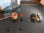
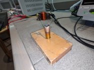
Has anyone tried using a solid wire coil with air cooling (fan) instead of tubing with water cooling. I just ran a test with 9 AWG magnet wire. The coil has an ID of 0.625 with a double helix with 8 turns on each layer. This coil seems to work very well at using only 28v, managing to melt a 44 mag case in only 3 seconds while drawing 20 amps. My only concern using this coil is how long I have to wait between cases to keep the coil cool enough and if over time will the radiant heat from the cases glowing red destroy the insulation on the wire. The insulation is rated to 200C. Using magnet wire allows the coil to have a smaller diameter and length for the same amount of turns not having to be concerned about shorting. This coil has an inductance only slightly greater than the coil that came with the board. The stock coil oscillated at 87KHz. This new magnet wire coil oscillates at 81KHz and the RMS voltage across the coil was 54.4 vac.
Attachments
I have both, PLC and ARDUINO controlled annealing machines. It would be "grand plaisir" to send you the codes, provided you publish yours .308 annealing results.Hi
Congratulations
On my annealer I use a PLC and I'd like to use an arduino instead the PLC.
How could I get your code?
Thanks a lot for your contribution
Patrice
Merci
I have had several requests for my Arduino code, so decided to post it here, feel free to ask any questions. Most of my previous coding was done in assembly language. This is the first coding I have done in over 30 years (and the first in C+) so it is not elegant by any means. I did check the run time for most routines and tried to optimize them for time where I could, as it seemed to produce a more consistent anneal.
C++:
// Version 6.3
// 05/31/2021
// Auto, Time, Joul and Pause modes.
// Streamlined Measure_A and Measure_V functions.
// Streamlined Measure_T by creating Convert_T.
// Added Measure_T back into Anneal_Sub.
// Added Convert_T to Error_Loop.
// Removed elapsed anneal time update durring Anneal_Sub.
// Function run time value comments updated.
// Start-up now Program 0 AUTO.

#include <Wire.h>
#include <EEPROM.h>
#include <elapsedMillis.h>
#include <JC_Button.h>
#include <OneWire.h>
#include "ABlocks_LiquidCrystal_I2C.h"

boolean b_Error = false;

char Print_Buffer[8] = "";

double Amperage = 0;
double Amp_Max = 0;
double Voltage = 0;
double Joules = 0;
const double Max_Amperes = 27.5;
const double V_Constant = 8.2750; // For resistors 51K and 6.8K,  57.8k/6.8k = 8.5 adjust as needed for accuracy

int Anneal_Time = 2500;
int Case_Program_Num = 0;
int Actual_Time = 0;
int Joule_Time = 0;
int Mode = 0;
int Anneal_Energy = 1200;
int Glow = 1023;
int Glow_Set = 50; // 1023 is dark, max glow is 0

int16_t C_Temp;
int16_t Last_Temp = 20;
const int A_Constant = 530; // Adjust as needed for accuracy
const int ls_Case_Name_size = 10;
const int Test_Anneal_Time = 2500;
const int Case_Settle = 500;
const int Drop_Delay = 10;
const int Door_Close = 10;
const int Detector_Threshold = 500; // Sets the detector trigger threshold of the IR receiver. 1000 = high
const int Fan_On_Temp = 120;
const int Test_Anneal_Energy = 1200;
const int Case_Glow_Program_Num = 20; // ls_Case_Name_size + 10

String s_Case_Text;
String s_Error_Text;
String s_Mode_Text;

//************************THIS IS WHERE YOU CUSTOMIZE CARTRIDGE CASE NAMES*****
//************************                                                   **
String ls_Case_Name[10] = { // 11 characters maximum                         **
  String("*AUTO MODE*"),    //                                               **
  String("NATO 5.56  "),    //                                               **
  String("6.5 PRC    "),    //                                               **
  String("300 WBY    "),    //                                               **
  String("Four       "),    //                                               **
  String("Five       "),    //                                               **
  String("Six        "),    //                                               **
  String("Seven      "),    //                                               **
  String("Eight      "),    //                                               **
  String("Test       ")};   //                                               **
//*****************************************************************************
//*****************************************************************************

LiquidCrystal_I2C lcd(0x27,20,4);

Button
  Tm_Up(2),   // Add time
  Tm_Dn(3),   // Subtract time
  Pgm_Up(4),  // Next program
  Pgm_Dn(5),  // Previous program
  Int_Err(6); // Interupt anneal and clear error

elapsedMillis Annealing; // Used to measure total annealing time
elapsedMillis Measuring; // Used to calculate joules

void fnc_EEPROM_updateDouble(int ee, double value) {
  byte* p = (byte*)(void*)&value;
  for (int i = 0; i < sizeof(value); i++)
  EEPROM.update(ee++, *p++);
}

double fnc_EEPROM_readDouble(int ee) {
  double value = 0.0;
  byte* p = (byte*)(void*)&value;
  for (int i = 0; i < sizeof(value); i++)
  *p++ = EEPROM.read(ee++);
  return value;
}

void EEPROM_Initialize() {
  fnc_EEPROM_updateDouble((int)(0*4),3000);
  fnc_EEPROM_updateDouble((int)(1*4),3000);
  fnc_EEPROM_updateDouble((int)(2*4),3000);
  fnc_EEPROM_updateDouble((int)(3*4),3000);
  fnc_EEPROM_updateDouble((int)(4*4),3000);
  fnc_EEPROM_updateDouble((int)(5*4),3000);
  fnc_EEPROM_updateDouble((int)(6*4),3000);
  fnc_EEPROM_updateDouble((int)(7*4),3000);
  fnc_EEPROM_updateDouble((int)(8*4),3000);
  fnc_EEPROM_updateDouble((int)(255*4),(-537537));
}

double Measure_A() { // 1m sec to run function, 30 amp sensor returns 66mA/V; 20 amp sensor, 100mA/V, both OA = 2.5V input
  Amperage = (analogRead(A1) - A_Constant) * 5 / 67.584; // Sensor returns 66mV/A (0.66x1024=67.584) Starts at 2.5V(511), adjust A_Constatnt for accuracy
  if (Amperage >= 0) {
    if (Amperage > Amp_Max)
      Amp_Max = Amperage;
  }
  else
    Amperage = 0;
}

double Measure_V() { // 1m sec to run function, Voltage sensor 6.8K and 51K reistors
  Voltage = analogRead(A0) * V_Constant * 5 / 1024;
  if (Voltage < 0)
    Voltage = 0;
}

int16_t Measure_T(int x, byte start) { // 6m sec to run function, DS18B20 Temperature Sensor 4.7K pullup rsistor on middle pin to +5
  OneWire ds(7);
  byte i;
  byte data[2];
  do {
    ds.reset();
    ds.write(0xCC); // Skip command
    ds.write(0xBE); // Read 1st 2 bytes of Scratchpad
    for (i=0; i<2; i++) data[i] = ds.read();
    C_Temp = (data[1]<<8) | data[0];
    C_Temp >>= 4;
    if (data[1] & 128) C_Temp |= 61440;
    if (data[0] & 8) ++C_Temp;
    ds.reset();
    ds.write(0xCC); //Skip command
    ds.write(0x44,1); //Start conversion, assuming 5V connected
    if (start) delay(1000);
  }
  while
    (start--);
  if (C_Temp >= 82) { // ZVS PCB opperating temperature -58F to 230F (-50C to 110C)
    digitalWrite(8,LOW);
    digitalWrite(10,HIGH);
    lcd.setCursor(17,1);
    lcd.print("MAX");
    s_Error_Text = String ("  TEMP HIGH ERROR!  ");
    b_Error = true;
  }
}

void Convert_T() { // 7m sec to run function
  Measure_T(7,0);
  double F_Temp;
  if (C_Temp <= Last_Temp - 20) //check for bogus data
    return;
  Last_Temp = C_Temp;
  F_Temp = C_Temp * 9 / 5 + 32; // Convert C to F adjust as needed for accuracy
  if
    (F_Temp >= Fan_On_Temp) digitalWrite(10,HIGH); // Turn fan on if temp gets high
  else
    digitalWrite(10,LOW);
  lcd.setCursor(17,1);
  dtostrf(F_Temp,3,0,Print_Buffer);
  lcd.print(Print_Buffer);
}

void Anneal_Sub() { // 1m sec to run function witout Measure_T, 6m sec with Measure_T
  Int_Err.read();
  Measure_T(7,0);
  Measure_A();
  Measure_V();
  Glow = analogRead(A3);
  Joule_Time = Measuring;
  Measuring = Measuring - Joule_Time;
  Joules = Joules + (Voltage * Amperage * Joule_Time / 1000);
  //lcd.setCursor(3,2);                              // These 3 update timer durring anneal
  //dtostrf(float(Annealing)/1000,4,2,Print_Buffer); // taking 8m sec to execute and were
  //lcd.print(Print_Buffer);                         // removed to speed-up Anneal_Sub
// Anneal manual button interrupt
  if (Int_Err.wasPressed()) {
    s_Error_Text = String (" ANNEAL INTERUPTED! ");
    b_Error = true;
    return;
  }
// Anneal over max amperes interrupt
  if (Amperage >= Max_Amperes) {
    s_Error_Text = String ("   AMP HIGH ERROR   ");
    b_Error = true;
  }
}

void Anneal_Main() {
  //int Func_Time; // Used for computing time of a function
  b_Error = false;
  Joules = 0;
  Amp_Max = 0;
  Glow = 1023;
  Convert_T();
  delay(Case_Settle);
  digitalWrite(8,HIGH); // SSR relay on
  Annealing = 0;
  Measuring = 0;
  lcd.setCursor(0,3);
  lcd.print("   ANNEALING CASE   ");
  if (Case_Program_Num == 0) {
    while (Glow > Glow_Set && !b_Error) {
      //elapsedMillis Timer;      // Used for computing time of a function
      Anneal_Sub();
      //Func_Time = Timer;        // Used for computing time of a function
      //s_Error_Text = Func_Time; // Used for computing time of a function
      //b_Error = true;           // Used for computing time of a function
    }
  }
  else if (Mode == 1) {
    while ((Annealing <= Anneal_Time - 10) && !b_Error) // Skip last 10m sec to avoid overshoot
      Anneal_Sub();
    while (Annealing < Anneal_Time && !b_Error)
      delay(1);
  }
  else
    while ((Joules < Anneal_Energy - 2) && !b_Error) // Skip last 2J to avoid overshoot
      Anneal_Sub();
// Anneal complete
  digitalWrite(8,LOW);
  Joule_Time = Measuring;
  Actual_Time = Annealing;
  Joules = Joules + (Voltage * Amperage * Joule_Time / 1000);
  lcd.setCursor(15,2);
  dtostrf(Joules,4,0,Print_Buffer);
  lcd.print(Print_Buffer);
  lcd.setCursor(3,2);
  dtostrf(float(Actual_Time)/1000,4,2,Print_Buffer);
  lcd.print(Print_Buffer);
  lcd.setCursor(9,1);
  dtostrf(Amp_Max,3,1,Print_Buffer);
  lcd.print(Print_Buffer);
  lcd.setCursor(10,2);
  dtostrf(Glow,4,0,Print_Buffer);
  lcd.print(Print_Buffer);
  Convert_T();
  if (b_Error)
      Error_Loop();
// Case detector
  do {
    digitalWrite(9,HIGH); // Trap door relay open
    lcd.setCursor(0,3);
    lcd.print(" *****CASE JAM***** ");
  }
  while
    (analogRead(A2) < Detector_Threshold);
  delay(Drop_Delay);
  digitalWrite(9,LOW); // Trap door relay close
  delay(Door_Close);
  lcd.setCursor(0,3);
  lcd.print("  WAITING FOR CASE  ");
}

void Error_Loop() {
  delay(26);
  do {
    lcd.setCursor(0,3);
    lcd.print(s_Error_Text);
    Convert_T();
    Int_Err.read();
  } while
    (!Int_Err.wasPressed());
  b_Error = false;
  delay(26);
}

void Anneal_Set() { // Set Anneal Time
  if (Case_Program_Num == 0) {
    Glow_Set = fnc_EEPROM_readDouble(Case_Glow_Program_Num*4);
    return;
  }
  if (Mode == 1) {
    if (Case_Program_Num != (ls_Case_Name_size - 1))
      Anneal_Time = fnc_EEPROM_readDouble(Case_Program_Num*4);
    else
      Anneal_Time = Test_Anneal_Time;
  }
  else // Set Anneal Energy
    if (Case_Program_Num != (ls_Case_Name_size - 1))
      Anneal_Energy = fnc_EEPROM_readDouble((Case_Program_Num + 10)*4);
    else
      Anneal_Energy = Test_Anneal_Energy;
}

void Anneal_Change() {
  if (Case_Program_Num == 0) {
    if (fnc_EEPROM_readDouble(Case_Glow_Program_Num*4) != Glow_Set)
      fnc_EEPROM_updateDouble((int)(Case_Glow_Program_Num*4),Glow_Set);
    return;
  }
  if (Mode == 1) {// Anneal Time Change
    if ((fnc_EEPROM_readDouble(Case_Program_Num*4) != Anneal_Time) && (Case_Program_Num != (ls_Case_Name_size - 1)))
      fnc_EEPROM_updateDouble((int)(Case_Program_Num*4),Anneal_Time);
  }
  else // Anneal_Energy_Change()
    if ((fnc_EEPROM_readDouble((Case_Program_Num + 10)*4) != Anneal_Energy) && (Case_Program_Num != (ls_Case_Name_size - 1)))
      fnc_EEPROM_updateDouble((int)((Case_Program_Num + 10)*4),Anneal_Energy);
}

void Display() { // 52m sec to run funtion
  s_Case_Text = ls_Case_Name[(Case_Program_Num)];
  lcd.setCursor(0,0);
  lcd.print(Case_Program_Num);
  lcd.setCursor(2,0);
  lcd.print(s_Case_Text);
  if (Case_Program_Num == 0)  {
    lcd.setCursor(14,0);
    lcd.print("G=");
    dtostrf(Glow_Set,4,0,Print_Buffer);
  }
  else if (Mode == 1) {
    lcd.setCursor(14,0);
    lcd.print("T=");
    dtostrf(float(Anneal_Time)/1000,4,2,Print_Buffer);
  }
  else {
    lcd.setCursor(14,0);
    lcd.print("J=");
    dtostrf(Anneal_Energy,4,0,Print_Buffer);
  }
  lcd.setCursor(16,0);
  lcd.print(Print_Buffer);
  Measure_V();
  lcd.setCursor(2,1);
  dtostrf(Voltage,3,1,Print_Buffer);
  lcd.print(Print_Buffer);
  Convert_T();
  if (b_Error)
    Error_Loop();
}

void setup() {
  if ((fnc_EEPROM_readDouble((int)(255*4)) != -537537))
    EEPROM_Initialize();
  Tm_Up.begin();     // Pin 2  Blue,   Add time
  Tm_Dn.begin();     // Pin 3  Purple, Subtract time
  Pgm_Up.begin();    // Pin 4  Yellow, Next program
  Pgm_Dn.begin();    // Pin 5  Green,  Previous program
  Int_Err.begin();   // Pin 6  Brown,  Interupt anneal and clear error
  Measure_T(7,1);     // Pin 7  Temperature sensor
  pinMode(8,OUTPUT); // Pin 8  SSR control
  pinMode(9,OUTPUT); // Pin 9  Trap door control
  pinMode(10,OUTPUT);// Pin 10 Fan
  pinMode(A0,INPUT); // Pin A0 Measure voltage
  pinMode(A1,INPUT); // Pin A1 Measure Amperage
  pinMode(A2,INPUT); // Pin A2 IR break beam
  pinMode(A3,INPUT); // Pin A3 Flame sensor
  lcd.begin();
  lcd.noCursor();
  lcd.clear();
  lcd.display();
  lcd.setCursor(1,0);
  lcd.print(":");
  lcd.setCursor(14,0);
  lcd.print("T=");
  lcd.setCursor(0,1);
  lcd.print("V=");
  lcd.setCursor(7,1);
  lcd.print("A=");
  lcd.setCursor(14,1);
  lcd.print("F=");
  lcd.setCursor(0,2);
  lcd.print("Ta=");
  lcd.setCursor(19,2);
  lcd.print("J");
  lcd.setCursor(8,2);
  lcd.print("G=");
  lcd.setCursor(0,3);
  lcd.print("  WAITING FOR CASE  ");
  digitalWrite(8,LOW); // Annealer power SSR
  digitalWrite(9,LOW); // Trap Door
  digitalWrite(10,LOW); // Fan
}

void loop() {
  Display();
  Tm_Up.read();   // Pin 2 Add time
  Tm_Dn.read();   // Pin 3 Subtract time
  Pgm_Up.read();  // Pin 4 Next program
  Pgm_Dn.read();  // Pin 5 Previous program
  Int_Err.read(); // Pin 6 Cycle Mode, interupt anneal and clear error
// Interup button pressed cycle mode, Mode 0 pause, Mode 1 time anneal, Mode 2 joule anneal
  if (Int_Err.wasPressed()) {
    if (Case_Program_Num == 0) {
      if (Mode != 0)
        Anneal_Change();
      if (++Mode > 1)
        Mode = 0;
    }
    else {
      if (Mode != 0) // Changing out of modes 1-3 check for value change
        Anneal_Change();
      if (++Mode > 2) // Cycle from Mode 2 back to Mode 0
        Mode = 0;
      if (Mode == 2) // Going from Mode 1 to Mode 2, set Joule value from EEPROM
        Anneal_Set();
    }
    Display();
  }
  if (Mode == 0) {
    s_Error_Text = String ("     PAUSE MODE     ");
    Error_Loop();
    Mode = 1;
    Anneal_Set(); // Going from Mode 0 to Mode 1, set Time value from EEPROM
    lcd.setCursor(0,3);
    lcd.print("  WAITING FOR CASE  ");
  }
// Up time/energy button pressed Pin 2
  if (Tm_Up.wasPressed()) {
    if (Mode == 1 && Case_Program_Num != 0) { //Max anneal time 9.99 seconds
      Anneal_Time = Anneal_Time + 50;
      if (Anneal_Time > 9950)
        Anneal_Time = 9990;
    }
    else if (Mode == 2 && Case_Program_Num != 0) { //Max anneal energy 9999 jouls
      Anneal_Energy = Anneal_Energy + 5;
      if (Anneal_Energy > 9999)
        Anneal_Energy = 9999;
    }
    else { // Max Glow_Set 1023
      if (++Glow_Set > 1023)
        Glow_Set = 1023;
    }
    Display();
  }
// Up time/energy button held Pin 2
  while (Tm_Up.pressedFor(750)) { //Max anneal time 9.99 seconds
    if (Mode == 1 && Case_Program_Num != 0) { //Max anneal time 9.99 seconds
      Anneal_Time = Anneal_Time + 50;
      if (Anneal_Time > 9950)
        Anneal_Time = 9990;
    }
    else if (Mode == 2 && Case_Program_Num != 0) { //Max anneal energy 9999 jouls
      Anneal_Energy = Anneal_Energy + 5;
      if (Anneal_Energy > 9999)
        Anneal_Energy = 9999;
    }
    else { // Max Glow_Set 1023
      if (++Glow_Set > 1023)
        Glow_Set = 1023;
    }
    Display();
    delay(50);
    Tm_Up.read();
  }
// Down time/energy button pressed Pin 3
  if (Tm_Dn.wasPressed()) { //Min anneal time 0.25 seconds
    if (Mode == 1 && Case_Program_Num != 0) {
      Anneal_Time = Anneal_Time - 50;
      if (Anneal_Time <= 250)
        Anneal_Time = 250;
    }
    else if (Mode == 2 && Case_Program_Num != 0) { //Min anneal energy 500 jouls
      Anneal_Energy = Anneal_Energy - 5;
      if (Anneal_Energy <= 100)
        Anneal_Energy = 100;
    }
    else { //Min Glow_Set 0
      if (--Glow_Set < 0)
        Glow_Set = 0;
    }
    Display();
  }
// Down time/energy button held Pin 3
  while (Tm_Dn.pressedFor(750)) {
    if (Mode == 1 && Case_Program_Num != 0) {
      Anneal_Time = Anneal_Time - 50;
      if (Anneal_Time <= 250)
        Anneal_Time = 250;
    }
    else if (Mode == 2 && Case_Program_Num != 0) { //Min anneal energy 500 jouls
      Anneal_Energy = Anneal_Energy - 5;
      if (Anneal_Energy <= 100)
        Anneal_Energy = 100;
    }
    else { // Min Glow_Set 0
      if (--Glow_Set < 0)
        Glow_Set = 0;
    }
    Display();
    delay(50);
    Tm_Dn.read();
  }
// Up program button pressed Pin 4
  if (Pgm_Up.wasPressed()) {
    Anneal_Change();
    if ((++Case_Program_Num > (ls_Case_Name_size - 1)))
      Case_Program_Num = 0;
    Anneal_Set();
    Display();
  }
// Down program button pressed Pin 5
  if (Pgm_Dn.wasPressed()) {
    Anneal_Change();
    if (--Case_Program_Num < 0)
      Case_Program_Num = (ls_Case_Name_size - 1);
    Anneal_Set();
    Display();
  }
// Case detector IR Emitter diode + 150 Ohm reistor to 5V, IR Receiver Diode + 10K to gnd
  if (analogRead(A2) < Detector_Threshold)
    Anneal_Main();
}
Last edited:
I have my case feeder pretty well sorted now, see the video below. If anyone wants to print their own, I've uploaded the STL files to Thingiverse. I've got versions to suit a Nema 17 stepper motor which I used as well as a generic 12v geared motor: https://www.thingiverse.com/thing:4902058
@VebatusDominos
I started learning Arduino C from this forum and I was delighted to read all 12 pages of your code. I did not go into details of some sections of the code (measuring annealing time for example) but it appears that you achieved quite well your concept of annealing control.
Questions:
- How did you measure the execution time of some of your routines?
- Never seen before Tm_Up.begin() and Tm_Up.read(). What do they do?
- What is the reason for Max_Amps?
- What is your ultimate Glow 0-1023?
Thanks for sharing your work!
The execution time of a routine was measured by starting a timer immediately before calling the routine and stoping the timer upon returning from the routine.@VebatusDominos
I started learning Arduino C from this forum and I was delighted to read all 12 pages of your code. I did not go into details of some sections of the code (measuring annealing time for example) but it appears that you achieved quite well your concept of annealing control.
Questions:
- How did you measure the execution time of some of your routines?
- Never seen before Tm_Up.begin() and Tm_Up.read(). What do they do?
- What is the reason for Max_Amps?
- What is your ultimate Glow 0-1023?
Thanks for sharing your work!
Tm_Up is the variable name I assigned to the button used to add time to the timer. I used the JC_Button.h library and the Tm_Up.begin() is used to initialize the button input and the Tm_Up.read() is the call to check to see if the button was pushed.
Max_Amps is used to stop the annealing process if the ZVS board draws more amps than the power supply is capable of supplying.
I found that a value of 50 for the glow setting was correct for my final set up. Durring testing of the glow function, the sensor was positioned closer to the case neck and the value was about 20. So you will have to do some testing with the glow value because it is dependent on the distance your sensor is to the case neck. The variable "int Glow_Set = 50" sets the initial value of the glow threshold each time you turn the annealer on. It is adjustable on the fly with the Tm_Up and Tm_dn buttons.
Last edited:
VenatusDominus,
Thank you for your detailed descriptions. I was very novice to note the existence of elapsedMillis.h and JC_Button.h libraries. I even tried to wright my own routines for Push Button de bouncing. Hope I'm not a pest for asking more questions.
Can you describe the algorithm for the annealing subs -
Joule_Time, Actual_Time , Anneal_Time?
And I'll be glad to publish my code, in the same format you did, provided I would know how.
Thanks again
How much variance in time and joules do you see if you use the flame sensor with close to identical brass, same caliber, make and lot? The flame sensor seems to use a pot to set the temperature to trigger on. So using the flame sensor the trick is adjusting the pot to the right value of heat and hopefully that setting applies to other types of cases well. The older method requires the user to test time settings to get the "right" value for a specific lot of cases.
Hello to all,
Another Frenchman from France sharing his work with you.
I wanted to thank all the participants of this topic and especially @Gina1 for having created this thread. Thanks also to @KeeWay for sharing files for the Arduino and Nextion code.
So I present you my first works on my machine which is in its second version:
On the other hand I have many questions about the annealing time and how to proceed. I really liked the scientific approach of @Patrice COTTES, your results were very interesting.
I'm not too much for the Tempilak method, I find it quite empirical, I'm satisfied for the moment to get the red emerging on the top of the neck.
I also like the system with the IR detector of @VenatusDominus . I have a question about this, what does this sensor detect? I could eventually implement it in my Arduino program to test it but it will require quite a bit of analysis of the KeeWay program.
In the meantime thank you very much for all your experience sharing, and I stay tuned to this thread and I could also help those who want to debug the Arduino program I use.
In the function Anneal_Sub():VenatusDominus,
Thank you for your detailed descriptions. I was very novice to note the existence of elapsedMillis.h and JC_Button.h libraries. I even tried to wright my own routines for Push Button de bouncing. Hope I'm not a pest for asking more questions.
Can you describe the algorithm for the annealing subs -
Joule_Time, Actual_Time , Anneal_Time?
And I'll be glad to publish my code, in the same format you did, provided I would know how.
Thanks again
Joule_Time is the variable used to represent the amount of time that has elapsed since the last time the Joules were calculated. Joules = voltage x amperes x time. Since the voltage and amperes are constantly changing durring the annealing process, it is more accurate to sample the voltage and amperes as often as possible in order to get a more accurate value for Joules. Each sampling of V and A are then multiplied by the amount of elapsed time since the last sampling and the result is added to the total joules. This is far more accurate than using a single sampling of V and A and multiplying by the total elapsed time.
Actual_Time is the variable used to represent the total elapse time of the annealing process, the actual total time that the coil was energized.
Anneal_Time is the variable used to represent the user's desired amount of time for annealing. When running in the timed mode, the user can adjust the amount of time (Anneal_Time) they would like the coil to be energized for. The actual time the coil is energized for is then tracked by Actual_Time. In the timed mode the actual time the coil was energized for (Actual_Time) will be equal to the desired time (Anneal_Time).
First of all, congratulations on your build. It looks very professional and polished!Hello to all,
Another Frenchman from France sharing his work with you.
I wanted to thank all the participants of this topic and especially @Gina1 for having created this thread. Thanks also to @KeeWay for sharing files for the Arduino and Nextion code.
So I present you my first works on my machine which is in its second version:
On the other hand I have many questions about the annealing time and how to proceed. I really liked the scientific approach of @Patrice COTTES, your results were very interesting.
I'm not too much for the Tempilak method, I find it quite empirical, I'm satisfied for the moment to get the red emerging on the top of the neck.
I also like the system with the IR detector of @VenatusDominus . I have a question about this, what does this sensor detect? I could eventually implement it in my Arduino program to test it but it will require quite a bit of analysis of the KeeWay program.
In the meantime thank you very much for all your experience sharing, and I stay tuned to this thread and I could also help those who want to debug the Arduino program I use.
The infrared flame sensors are designed to detect light at the wavelength of 760nm to 1100nm and at a distance of up to 80cm. They are designed to be used for fire alarms. The particular sensor that I used has an adjustable pot that is used in conjunction with the analog output of the sensor and the sensitivity is adjustable this way. In addition, the sensor has a digital output between 0-1023 (1023 = no light, 0 = full light). The amount of light and the distance to the light both affect the digital output, as does any ambient light in the specified range. For my set up I used the digital output and found a value of 50 to work at the distance my sensor is mounted from the case neck.
Similar threads
- Replies
- 74
- Views
- 47,299
- Replies
- 0
- Views
- 1,572
Upgrades & Donations
This Forum's expenses are primarily paid by member contributions. You can upgrade your Forum membership in seconds. Gold and Silver members get unlimited FREE classifieds for one year. Gold members can upload custom avatars.

Click Upgrade Membership Button ABOVE to get Gold or Silver Status.
You can also donate any amount, large or small, with the button below. Include your Forum Name in the PayPal Notes field.
To DONATE by CHECK, or make a recurring donation, CLICK HERE to learn how.
Click Upgrade Membership Button ABOVE to get Gold or Silver Status.
You can also donate any amount, large or small, with the button below. Include your Forum Name in the PayPal Notes field.
To DONATE by CHECK, or make a recurring donation, CLICK HERE to learn how.