• This Forum is for adults 18 years of age or over. By continuing to use this Forum you are confirming that you are 18 or older. No content shall be viewed by any person under 18 in California.

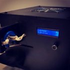
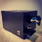
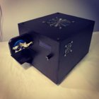
Induction brass annealer redux

Hi guys,

For those of you that have done multiple cases... In reality... How much adjustment is needed on the shelf (height wise) ?

The sky is the limit with Arduino. Arduino was the reason I built a second annealer. Unfortunately, I missed the idea of using touch screen. May be I would start a third built.

Regarding the adjustments, my base was from 50 caliber to .223. I'm using two synchronized step motors (one common control from Arduino) to move the trap gate platform up and down. Counting/storing the revolutions helps creating data base for each caliber - just activate the step motors to the next stop.
Regarding the solenoids, I replaced them very nicely with a step motor
HAVE FUN!
 
Added a "Analyze" routine to my software.
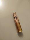
It asks for 5 cases to insert and anneals them to melting point , drops the case 0.4 seconds after max current. (image 1)
From average melting-time the anneal time is calculated (image 2 + 3)

eg 8.1 sec gives me 4.0 sec


This is an excellent approach... But I don't think this is the way the AMP machine does it... I could be wrong, but my reasons:

With the AMP, you insert the case upside down into the machine... If they do "melt" the case, this could cause molten brass to drip inside the machine... Or does the current drop before the case actually melts?

Also, with the AMP, the coil is completely closed off inside with a cover... And when you insert the case upside down, you also have a fitting on the case head that "plugs" the hole... This means that it is completely dark inside the machine once the case is inserted... I think they use some sort of light sensor to sense light caused by the case glowing hot?

But nevertheless... Good job @LR88 and I think I might implement the same :) :)
 
This is an excellent approach... But I don't think this is the way the AMP machine does it...

There's a link to their patent application for Aztec earlier in the thread where they drop a LOT of clues about how they're doing it. LR88 may not be doing it EXACTLY like AMP is doing it, but it's similar enough. They're definitely not using a light sensor and trying to watch for the glow of the case.

In fact, if you dig back through the history of the device, AMP didn't design their annealer with Aztec in mind at all. They found later that they already had all the sensors they needed designed in to the AMP already to do Aztec. What other purpose would a light sensor have in the device?

Edit to add - you can find pictures of cases that have been through an Aztec calibration on the web, too. They're DEFINITELY melted. They just push it right to the point where the case begins to melt, so it doesn't go molten inside the AMP.
 
My shelf was directly based off of @SGK's file with several adjustments to account for how far my coil extended off the enclosure face. Anyone thinking about doing this should take heed of SGK's advice:
Yes, sure. My advice is to think through the complete design before fiddling with files though. You have to figure out how everything is going to be mounted within the enclosure, how you are going to support the shelf etc.
I made the mistake of not making the shelf a primary thought and constraint in my unit's design and consequently needed to design the shelf around the already established coil placement/center, instead of placing the coil in relation to the shelf. The latter method would have been much more forgiving. Le$$on learned... :oops:
My shelf is "tailor fit" to my annealer in terms of dimensions and may not be of much use to you per say, @SinWolf, but I can still post it if you'd like.
 
Last edited:
"... figure out their complete design first..." (advice from SGK and dulcimer)

This is excellent advice. It is easy to paint yourself into a corner by not considering the whole design. The devil is in the details... This is especially true if you don't have your own 3d printer. Reprinting a few dollars of plastic isn't a big deal, but ordering commercial printing costs a factor of 20 or so over the material costs. So it becomes much more important to be precise, and to be prepared for one or two rework cycles in the cost planning.

Someone asked about the differential height of the case support. If you consider that the shoulder should be at the same height inside the coil you can see how your cartridges differ. This may not be perfect but it should be close. In my case the range from 300 win mag to 7mm TCU is about 18mm (nearly 3/4 inch). So I'm looking at different designs that have an easily replaceable cartridge support component to accommodate varying height and diameter heads with a specific funnel customized to each case rather than the shelf/solenoid. There's more than one way to solve many of these issues. I'm still considering various options. Using standard low cost metal gear RC servos makes it easy to get motors, and easy to control them as they contain the power drivers and only a single wire is required to request the position as they contain closed loop feedback internally. It is easy for a microcontroller to generate the required control pulses, standard libraries are available so very little code is required. There are plenty of examples of this type of control on the internet.


upload_2020-5-27_11-9-51.png
 
Thanks for all the responses!!

I love these kind of DIY projects, and I'm well aware of the amount of planning that needs to go into a project like this to prevent re-work.

I will make 100% sure of everything before I start with the enclosure manufacturing and the 3D printing...

When I tackle projects like these, I like to do the design in such away as to "easily" re=produce the end product... This means that I try to avoid doing custom parts in my garage, as these parst are not easily "repeatable"...

I still have a long way to go...

BUT THANKS EVERYBODY for your willingness to share info...

I still have an issue trying to compile @KeeWay Arduino code. I have solved some issues, but there are other issues I'm having difficulty with... I will modify the code to suit my design, but I would like to have a working code to start from... So if anybody can send me their design (including libraries), I will really appreciate this...
 
There's a link to their patent application for Aztec earlier in the thread where they drop a LOT of clues about how they're doing it. LR88 may not be doing it EXACTLY like AMP is doing it, but it's similar enough. They're definitely not using a light sensor and trying to watch for the glow of the case.

In fact, if you dig back through the history of the device, AMP didn't design their annealer with Aztec in mind at all. They found later that they already had all the sensors they needed designed in to the AMP already to do Aztec. What other purpose would a light sensor have in the device?

Edit to add - you can find pictures of cases that have been through an Aztec calibration on the web, too. They're DEFINITELY melted. They just push it right to the point where the case begins to melt, so it doesn't go molten inside the AMP.


Awesome... Thanks for the info :)

I will definitely implement the "analyze" procedure in my build.
 
The solenoid may only have 10 mm travel but it depends on you design. If you use a straight pull base you can only have up to 10 mm cartridges but if you use a L shape trap door and get the right orientation of the solenoid you can get a really big swing at the end of the trap door base plate.

I have made a few posts re Ferrite models it you do a search.
 
I found a seller on eBay offering discounted Mean Well RSP-750-48 (750W/48V/15.7A with current limiting functions) power supplies for about $130 before s/h&t. Ships from Cali.
Upgrading from my SE-600-48...
Edit: 8 left
https://www.ebay.com/itm/MEAN-WELL-RSP-750-48-750W-48V-Switching-Power-Supply/192869526398

<div style="width:100%;height:0px;position:relative;padding-bottom:56.250%;"><iframe src="https://streamable.com/e/4i6ksq" frameborder="0" width="100%" height="100%" allowfullscreen style="width:100%;height:100%;position:absolute;left:0px;top:0px;overflow:hidden;"></iframe></div>
 
Last edited:
Anyone wanting help with Arduino code I've attached a copy of my latest code. Still has some commented out sections relating to a servo that I since replaced with a rotary solenoid. This uses a 4x20 LCD with a rotary knob for user control and input. The rotary knob with push button has 3 built in LED's that can be programmed for visual indication as well. Next revision I want to make a menu selection screen so what is shown while running can be customized. Currently I have two displays that can be selected on startup that flip flop back in forth depending on if I am adjusting the time up vs down. I have a flow meter and two thermistors as well as the standard amps and volts input. Also have fan RPM and PWM control on one fan. All the I/O is used up without going to a MEGA controller. With this program you can adjust the setpoint while annealing and also abort by pressing the button, this is useful if you start seeing things glow red and your not sure what the time needed to be to start with (the abort time is displayed so you can use that as the time needed). Peek amps are captured as well and the last time setpoint is saved when shutdown.

This is overkill for the task but its more about experimenting and having some fun along the way.


Code:
/**********************************
 * Annealing Circuit              *
 * By SMO 07/25/2018              *
 **********************************/

#include <Button.h> //note that this is a different version than the standard button help, it can be found at https://github.com/slavianp/improc/tree/master/Arduino/src/Library
#include <TicksPerSecond.h> // this can be found at https://github.com/slavianp/improc/tree/master/Arduino/src/Library
#include <RotaryEncoderAcelleration.h> // this can be found at https://github.com/slavianp/improc/tree/master/Arduino/src/Library
#include <Metro.h>
#include <elapsedMillis.h>
#include <LiquidCrystal_I2C.h>
//#include <Servo.h>
#include <EEPROM.h>
#include <PinChangeInterrupt.h>
#include <PID_v1.h>
#include <PWM.h>

// Assign I/O pins (Traffic Cop)
#define Encoder_A_Pin 2
#define Encoder_B_Pin 3
#define Encoder_Button_Pin 4
#define Encoder_LED_BLU_Pin 11
#define Encoder_LED_GRN_Pin 12
#define Encoder_LED_RED_Pin 13  // Note that LED is also on pin 13, avoid using as input except UNO board with buffer to LED
#define Case_Sensor_Pin 5
#define Relay_Output_Pin 6
#define Solenoid_Pin 7
//#define Drop_Servo_Pin 7
#define Flow_Sensor_Pin 8
#define Fan_PWM_Pin 9 // analogwrite pins on ATmega328p can only be on 3,5,6,9,10&11
#define Fan_RPM_Pin 10


#define Analog_Amps_Pin A0
#define Analog_Volt_Pin A1
#define Analog_Temp1_Pin A2
#define Analog_Temp2_Pin A3

// Thermistor Values
#define Thermistor_Nom     10000 //Resistance at 25 DegC
#define Thermistor_Temp    25    //Nominal temperature in DegC
#define Thermistor_Beta    3435  //Beta coefficient for thermistor
#define Thermistor_Res     10000 //Value of resistor in series with thermistor

// Initialize I/O values
boolean Relay_State = LOW;
boolean Pushbutton_State = LOW;
boolean Case_Sensor_State = LOW;
boolean Solenoid_State = LOW;
float Analog_Pot_Val = 0;
float Analog_Volt_Val = 0;
float Analog_Amps_Val = 0;
float Max_Amps_Val = 0;
float Analog_Temp1_Val = 0;
float Temp1_Steinhart_Val = 0;
float Analog_Temp2_Val = 0;
float Temp2_Steinhart_Val = 0;

// Initialize other values
int Seq_Step_Num = 1;
int Timer_Setpt = 0;
int Timer_Display = 0;
int Load_Delay_Setpt = 0500; //Delay time in mSEC, gives time for a brass to get into position for annealing
int Drop_Delay_Setpt = 0010; //Delay time in mSEC, gives time for the servo to get into drop position
int Case_Delay_Setpt = 0500; //Delay time in mSEC, gives time for brass to drop and clear the servo
int Home_Delay_Setpt = 0010; //Delay time in mSEC, gives time for the servo to get into home position
int Drop_Pos_Setpt = 90; //in degrees
int Home_Pos_Setpt = 0; //in degrees
volatile long Flow_Total = 0;
volatile long Flow_Interlock_Total = 0;
int Flow_Interlock_Val = 0;
float Flow_Rate = 0;
volatile boolean Button_Toggle_State = 0;
float Joules_Total = 0;
volatile long Fan_RPM_Total = 0;
int Fan_RPM_Rate = 0;
boolean Encoder_Inc = LOW;

// Set Memory location for last time setpoint, setpoint will be saved when power is down
int eeAddress = 0;
float eeData = 0;

// Setup PID for Fan Control
double PID_SP=1000, PID_PV, PID_OP, PID_Kp=2, PID_Ki=0.1, PID_Kd=.5; //Setpoint is multiplied by 10, example 950=95.0 degF
PID FanPID(&PID_PV, &PID_OP, &PID_SP, PID_Kp, PID_Ki, PID_Kd, REVERSE);

// Sequence Descriptions
char *Seq_Step_Desc[] = {
// 12345678901234567892  20 characters max
  "Step 0; not used    ",
  "Step 1; press start ",
  "Step 2; load case   ",
  "Step 3; load delay  ",
  "Step 4; start anneal",
  "Step 5; time anneal ",
  "Step 6; stop anneal ",
  "Step 7; drop pos    ",
  "Step 8; drop delay  ",
  "Step 9; case clear? ",
  "Step10; clear delay ",
  "Step11; home pos    ",
  "Step12; home delay  ",
  "Step13; Return      ",
  "Step14; Check Flow  ",
  "Step15; HIGH AMPS   "
};

// Set the LCD address and 20x4 display also define extra characters
LiquidCrystal_I2C lcd(0x20, 20, 4);
char Print_Buffer[40] = "";
#if defined(ARDUINO) && ARDUINO >= 100
#define printByte(args)  write(args);
#else
#define printByte(args)  print(args,BYTE);
#endif
uint8_t Up_Arrow[8] = {0x04, 0x0E, 0x15, 0x04, 0x04, 0x04, 0x04, 0x00}; //Define Up Arrow for LCD
uint8_t Dn_Arrow[8] = {0x00, 0x04, 0x04, 0x04, 0x04, 0x15, 0x0E, 0x04}; //Define Down Arrow for LCD

//Configure Metro Objects
Metro LCD_Print_Data = Metro(10);
Metro Analog_Inputs_Read = Metro(10);
Metro Flow_Calculation = Metro(10000);
Metro Flow_Interlock = Metro(1000);
Metro Joules_Calculation = Metro(100);
Metro Fan_RPM_Calculation = Metro(6000);

//Configure Timers
elapsedMillis Timer_Actual;
elapsedMillis Button_Debounce;

//Configure Servos
//Servo Drop_Servo;

//Configure Encoder
RotaryEncoderAcelleration Encoder_Knob;

void UpdateEncoder(){
  Encoder_Knob.update();
}

/***************************
 * Setup Program Begin     *
 ***************************/
void setup() {
  //Assign pin modes
  pinMode(Relay_Output_Pin, OUTPUT);
  pinMode(Solenoid_Pin, OUTPUT);
  pinMode(Fan_PWM_Pin, OUTPUT);
  pinMode(Fan_RPM_Pin, INPUT_PULLUP);
  pinMode(Case_Sensor_Pin, INPUT_PULLUP);
  pinMode(Flow_Sensor_Pin, INPUT_PULLUP);
  pinMode(Encoder_Button_Pin, INPUT);
  pinMode(Encoder_LED_BLU_Pin, OUTPUT);
  pinMode(Encoder_LED_GRN_Pin, OUTPUT);
  pinMode(Encoder_LED_RED_Pin, OUTPUT);

  //Get last setpoint before power down to set initial encoder setpoint
  EEPROM.get(eeAddress, eeData);

  //Initialize Encoder
  Encoder_Knob.initialize(Encoder_A_Pin, Encoder_B_Pin);
  Encoder_Knob.setMinMax(50, 2000);
  Encoder_Knob.setPosition(eeData); //Initialize Encoder Position with saved data
  attachInterrupt(0, UpdateEncoder, CHANGE);
 
  //Initialize LCD
  lcd.begin();
  lcd.backlight();
  lcd.createChar(0, Up_Arrow);
  lcd.createChar(1, Dn_Arrow);

  //Set initial postion for Drop Servo
  /*
  Drop_Servo.attach(Drop_Servo_Pin);
  Drop_Servo.write(Drop_Pos_Setpt);
  delay(Drop_Delay_Setpt);
  Drop_Servo.write(Home_Pos_Setpt);
  delay(Drop_Delay_Setpt);
  */

  //Setup PID
  FanPID.SetOutputLimits(100, 255);
  FanPID.SetMode(AUTOMATIC);

  //Setup PWM frequency
  InitTimersSafe(); //Initialize all timers except for 0, to save time keeping functions
  SetPinFrequencySafe(Fan_PWM_Pin, 25000); //Set frequency to 25khz
 
  //Set the flow meter pin change interrupt
  attachPinChangeInterrupt(digitalPinToPinChangeInterrupt(Flow_Sensor_Pin), Flow_Rising, RISING);

  //Sense positive transition of button interrupt
  attachPinChangeInterrupt(digitalPinToPinChangeInterrupt(Encoder_Button_Pin), Push_Button_Toggle, RISING);

  //Set the fan RPM pin change interrupt
  attachPinChangeInterrupt(digitalPinToPinChangeInterrupt(Fan_RPM_Pin), Fan_RPM_Rising, RISING);
}


/***************************
 * Main Program Loop Begin *
 ***************************/
void loop() {
  //Write Digital Outputs
  digitalWrite(Relay_Output_Pin, Relay_State);
  digitalWrite(Solenoid_Pin, Solenoid_State);

  // Read Digital Inputs
  // Pushbutton_State = !digitalRead(Pushbutton_Pin);  //this button is normally closed
  Pushbutton_State = digitalRead(Encoder_Button_Pin);  //this button is normally open
  Case_Sensor_State = digitalRead(Case_Sensor_Pin); //This sensor is normally open

  // Read Analog & Do PID's
  if(Analog_Inputs_Read.check() == 1){
    //To smooth analog signals use a single Pole Digital Filter [out=wt*out+(1-wt)*new]
    Analog_Amps_Val = 0.50 * Analog_Amps_Val + 0.50 * ((analogRead(Analog_Amps_Pin) / 1023.0 * 5000.0 - 5000.0/2.0)/100.0);
    Analog_Volt_Val = 0.75 * Analog_Volt_Val + 0.25 * (analogRead(Analog_Volt_Pin) * 0.079101); // span is 80 volts or 80/1023=0.078201 adjust as needed for accuracy
    Analog_Temp1_Val = 0.95 * Analog_Temp1_Val + 0.05 * (10000.0 / ((1023.0 / analogRead(Analog_Temp1_Pin)) - 1));
    Temp1_Steinhart_Val = Analog_Temp1_Val / Thermistor_Nom;
    Temp1_Steinhart_Val = log(Temp1_Steinhart_Val);
    Temp1_Steinhart_Val /= Thermistor_Beta;
    Temp1_Steinhart_Val += 1.0 / (Thermistor_Temp + 273.15);
    Temp1_Steinhart_Val = 1.0 / Temp1_Steinhart_Val;
    Temp1_Steinhart_Val -= 273.15;
    Temp1_Steinhart_Val = Temp1_Steinhart_Val * 1.8 + 32.0;
    PID_PV = Temp1_Steinhart_Val * 10.0;
    FanPID.Compute();
    pwmWrite(Fan_PWM_Pin, PID_OP);
    Analog_Temp2_Val = 0.95 * Analog_Temp2_Val + 0.05 * (10000.0 / ((1023.0 / analogRead(Analog_Temp2_Pin)) - 1));
    Temp2_Steinhart_Val = Analog_Temp2_Val / Thermistor_Nom;
    Temp2_Steinhart_Val = log(Temp2_Steinhart_Val);
    Temp2_Steinhart_Val /= Thermistor_Beta;
    Temp2_Steinhart_Val += 1.0 / (Thermistor_Temp + 273.15);
    Temp2_Steinhart_Val = 1.0 / Temp2_Steinhart_Val;
    Temp2_Steinhart_Val -= 273.15;
    Temp2_Steinhart_Val = Temp2_Steinhart_Val * 1.8 + 32.0;
  }

  // Calculate Flow Rate
  if(Flow_Calculation.check() == 1){
    Flow_Rate = (Flow_Total / 10.0) * 0.68913; //Flow meter; 1380 pulses/Liter or 5224 pulses/gal, gph = pps * 3600/5224 or .68913
    Flow_Total = 0;
  }
 
  // Calculate Flow Interlock
  if(Flow_Interlock.check() == 1){
    Flow_Interlock_Val = Flow_Interlock_Total;
    Flow_Interlock_Total = 0;
  }

  // Calculate Fan RPM's
  if(Fan_RPM_Calculation.check() == 1){
    Fan_RPM_Rate = Fan_RPM_Total * 10 / 2;
    Fan_RPM_Total = 0;
  }
 
  // Read Encoder
  long Encoder_Val = Encoder_Knob.getPosition();
  if(Seq_Step_Num == 1){
    Encoder_Inc = Encoder_Knob.isIncrementing();
  }

  // Calculate Timer Setpoint
  Timer_Setpt = float(Encoder_Val) * 10.0;

  // Calculate Joules (not accurate because of analog reading can only occur so fast)
  if(Joules_Calculation.check() == 1 & Seq_Step_Num == 5){
    Joules_Total = Joules_Total + Analog_Amps_Val * Analog_Volt_Val * 0.100;
  }

  // Set Debounce timer to max value to avoid rollover of value
  if(Button_Debounce >= 10000){
    Button_Debounce = 10000;
  }

  // Begin Sequence Logic
  switch(Seq_Step_Num){
    // Step 1 Wait for pushbutton toggle ON
    case(1):
      //Encoder LED's are reverse logic, Zero is ON
      digitalWrite(Encoder_LED_BLU_Pin, 1);
      digitalWrite(Encoder_LED_GRN_Pin, 1);
      digitalWrite(Encoder_LED_RED_Pin, 1);
      if(Button_Toggle_State == HIGH){
        //Encoder LED's are reverse logic, Zero is ON
        digitalWrite(Encoder_LED_BLU_Pin, 1);
        digitalWrite(Encoder_LED_GRN_Pin, 0);
        digitalWrite(Encoder_LED_RED_Pin, 1);
        Seq_Step_Num++;
        break;
      }
      break;
   
    // Step 2 Wait for Case, also store setpoint if changed
    case(2):
      //Only store new setpoint if it has changed
      if(eeData != Timer_Setpt){
        eeData = Timer_Setpt / 10.0;
        EEPROM.put(eeAddress, eeData);
      }
      if(Case_Sensor_State == LOW){
        Timer_Actual = 0;
        Seq_Step_Num++;
        break;
      }
      if(Button_Toggle_State == LOW){
        Seq_Step_Num = 1;
        break;
      }
      break;
 
    // Step 3 Wait for Load Case Delay
    case(3):
      if(Case_Sensor_State == LOW & Timer_Actual >= Load_Delay_Setpt){
        Seq_Step_Num++;
        break;
      }
      if(Case_Sensor_State == HIGH){
        Seq_Step_Num = 2;
        break;
      }
      break;

    // Step 4 Initialize annealing timer and Energize Relay
    case(4):
      Timer_Actual = 0;
      Max_Amps_Val = Analog_Amps_Val;
      Relay_State = HIGH;
      Joules_Total = 0;
      Joules_Calculation.reset();
      //Encoder LED's are reverse logic, Zero is ON
      digitalWrite(Encoder_LED_BLU_Pin, 1);
      digitalWrite(Encoder_LED_GRN_Pin, 1);
      digitalWrite(Encoder_LED_RED_Pin, 0);
      Seq_Step_Num++;
      break;

    // Step 5 Wait for Timer at Setpoint
    case(5):
      Timer_Display = Timer_Actual;
      Max_Amps_Val = Analog_Amps_Val;
      if(Timer_Actual >= Timer_Setpt || Button_Toggle_State == LOW){
        Timer_Display = Timer_Actual;
        Seq_Step_Num++;
        break;
      }
      // if the amps go high then goto step 15
      if(Analog_Amps_Val > 14.0){
        Seq_Step_Num = 15;
        break;
      }
      // if low flow then goto step 14
      if(Flow_Interlock_Val <= 4){
        Seq_Step_Num = 14;
        break;
      }  
      break;

    // Step 6 Denergize Relay
    case(6):
      Relay_State = LOW;
      //Encoder LED's are reverse logic, Zero is ON
      digitalWrite(Encoder_LED_BLU_Pin, 0);
      digitalWrite(Encoder_LED_GRN_Pin, 1);
      digitalWrite(Encoder_LED_RED_Pin, 1);
      Seq_Step_Num++;
      break;

    // Step 7 Set Drop Servo to drop position & Reset Timer
    case(7):
      Timer_Actual = 0;
      //Drop_Servo.write(Drop_Pos_Setpt);
      Solenoid_State = HIGH;
      Seq_Step_Num++;
      break;

    // Step 8 Wait for drop position
    case(8):
      if(Timer_Actual >= Drop_Delay_Setpt){
        Seq_Step_Num++;
        break;
      }
      break;

    // Step 9 Check for case clear & Reset Timer
    case(9):
      Timer_Actual = 0;
      if(Case_Sensor_State == HIGH){
        Seq_Step_Num++;
        break;
      }
      break;

    // Step 10 Wait for case to clear
    case(10):
      if(Timer_Actual >= Case_Delay_Setpt){
        Seq_Step_Num++;
        break;
      }
      break;
   
    // Step 11 Set Servo to Home Position & Reset Timer
    case(11):
      Timer_Actual = 0;
      //Drop_Servo.write(Home_Pos_Setpt);
      Solenoid_State = LOW;
      Seq_Step_Num++;
      break;

    // Step 12 Wait for servo home
    case(12):
      if(Timer_Actual >= Home_Delay_Setpt){
        Seq_Step_Num++;
        break;
      }
      break;

    // Step 13 Return to Step 1
    case(13):
      if(Button_Toggle_State == HIGH){
        digitalWrite(Encoder_LED_BLU_Pin, 1);
        digitalWrite(Encoder_LED_GRN_Pin, 0);
        digitalWrite(Encoder_LED_RED_Pin, 1);
        Seq_Step_Num = 2;
        break;
      }
      else{
        Seq_Step_Num = 1;
        break;
      }
      break;

    // Step 14 Check for flow
    case(14):
      Relay_State = LOW;
      //Encoder LED's are reverse logic, Zero is ON
      digitalWrite(Encoder_LED_BLU_Pin, 0);
      digitalWrite(Encoder_LED_GRN_Pin, 1);
      digitalWrite(Encoder_LED_RED_Pin, 1);
      if(Button_Toggle_State == LOW){
        Seq_Step_Num = 7;
        break;
      }
      break;

    // Step 15 HIGH AMPS
    case(15):
      Relay_State = LOW;
      //Encoder LED's are reverse logic, Zero is ON
      digitalWrite(Encoder_LED_BLU_Pin, 0);
      digitalWrite(Encoder_LED_GRN_Pin, 1);
      digitalWrite(Encoder_LED_RED_Pin, 1);
      if(Button_Toggle_State == LOW){
        Seq_Step_Num = 7;
        break;
      }
      break;
  }
 
  // Write to LCD Display except for last 150mSec of timer to prevent overshoot from writing to I2C, didn't want the complexity of a timer interrupt
  if(LCD_Print_Data.check() == 1 && (Timer_Actual <= Timer_Setpt - 150 || Seq_Step_Num != 5)){
    //1st LCD Row
    lcd.home();
    lcd.print("Set;");
    lcd.setCursor(4,0);
    dtostrf(float(Timer_Setpt)/1000, 5, 2, Print_Buffer);
    lcd.print(Print_Buffer);
    lcd.print(" Act ");
    dtostrf(float(Timer_Display)/1000, 6, 3, Print_Buffer);
    lcd.print(Print_Buffer);

    //2nd LCD Row
    lcd.setCursor(0,1);
    dtostrf(Analog_Volt_Val, 4, 1, Print_Buffer);
    lcd.print(Print_Buffer);
    lcd.print("V");
    lcd.setCursor(6,1);
    if(Encoder_Inc){
      dtostrf(Fan_RPM_Rate, 4, 0, Print_Buffer);
      lcd.print(Print_Buffer);
      lcd.print("RPM");
    }
    else{
      dtostrf(Joules_Total, 5, 0, Print_Buffer);
      lcd.print(Print_Buffer);
      lcd.print("J ");
    }
    lcd.setCursor(13,1);
    if(Seq_Step_Num == 5){
      dtostrf(Analog_Amps_Val, 5, 1, Print_Buffer);
      lcd.print(Print_Buffer);
      lcd.print(" A");
    }
    else{
      dtostrf(Max_Amps_Val, 5, 1, Print_Buffer);
      lcd.print(Print_Buffer);
      lcd.printByte(0); //Print Up Arrow
      lcd.print("A");
    }

    //3rd LCD Row
    lcd.setCursor(0,2);
    if(Encoder_Inc){
      lcd.print("T1;");
      dtostrf(Temp1_Steinhart_Val, 5, 1, Print_Buffer);
      lcd.print(Print_Buffer);
      lcd.print("F  ");
      lcd.setCursor(11,2);
      lcd.print("T2;");
      dtostrf(Temp2_Steinhart_Val, 5, 1, Print_Buffer);
      lcd.print(Print_Buffer);
      lcd.print("F");
    }
    else{
      lcd.print("F; ");
      dtostrf(Flow_Rate, 4, 1, Print_Buffer);
      lcd.print(Print_Buffer);
      lcd.print(" gph  ");
      lcd.setCursor(13,2);
      if(Case_Sensor_State == LOW){
        lcd.print("Case; Y");
      }
      else{
        lcd.print("Case; N");
      }
    }

    //4th LCD Row
    lcd.setCursor(0,3);
    lcd.print(Seq_Step_Desc[Seq_Step_Num]);
  }
}

/***************************
 * Flow Meter Interrupt    *
 ***************************/
 void Flow_Rising(void){
  Flow_Total++;
  Flow_Interlock_Total++;
 }

/***************************
 * Fan RPM Interrupt       *
 ***************************/
 void Fan_RPM_Rising(void){
  Fan_RPM_Total++;
 }

/*********************************
 * Positive Transition Sense     *
 *********************************/
void Push_Button_Toggle(void){
  if(Button_Debounce >= 1000){
    if(Button_Toggle_State == HIGH && Button_Debounce >= 100){
      Button_Toggle_State = LOW;
    }
    else{
      Button_Toggle_State = HIGH;
    }
    Button_Debounce = 0;
  }
}
Hi Ottsm, can you please post the code as a text file, I cant copy the code from the separate window. What component are you using for the case detector?
Ive just started a new build using an arduino, first time use but getting there bit by bit. Im reading all parameters from the eeprom. Tge code checks if the eeprom matches the program, if not it writes the hard coded values to it. The code also checks what set of parameters to use, ive only coded 2 options and these are read, and can be updated, to the eeprom. Fancy way to replicate the 4 stage timer relay really. Thanks in advance.
 
This would also be cool, if you can work it out! Keep us posted - I'd love to learn more about how you go about it!
I logged some data on 3 different cases (Norma 6.5x55, Norma .308 and Lapua 6.5x47) using Serial.print to print a row of comma separated values for every 1/10 second of the first second of a "normal" annealing. The rows contained Annealing target time (What I consider good) and the currents measured every 1/10 second.
I copy pasted the values into an online multiple regression analysis tool (http://www.xuru.org/rt/MLR.asp#CopyPaste) and started to fiddle with the data (too many columns, not enough rows). I had to remove some of the columns and decided to test what would happen if I only used 3 current measurements - and picked the ones made at 0.2, 0.6 and 1.0 second. The results were horrible, half of the calculated (predicted) target times were off by 3-4 tenths of a second. Then I decided to add info on caliber (diameter) and placement in coil (elevation of the bottom support of the case - the floor/table..) - and the errors of the predicted times compared to expected (the known good ones) were reduced to few hundreds of a second or a lot less. So, with the limited amount of data, and only having tested on 3 different types of cases, a model has been made, which as it seems right now, can predict with certainty, the "perfect" annealing time of any case among the three types I tested ;)
More testing to do in the weekend.
y is target time (ms)
x1 is expression for location in coil, I use some "riser" plates, in 3 thicknesses, 1, 2, and 3, 6 is 1+2+3, 7 is 2x3+1
x2 is caliber diameter
x3, x4 and x5 are currents measured at 0.2, 0.6 and 1.0 s
Screenshot 2020-05-29 at 22.48.48.png
 
Last edited:
Hi Ottsm, can you please post the code as a text file, I cant copy the code from the separate window.

Weird, I was able to copy it straight away?

Funny side note... I missed that you were quoting ottsm, and was reading through the code thinking, "ah, someone else grabbed ottsm's code, too!" Ha ha... I started off with his code as a building block, myself!

Just for interest - my code is still in a state of flux, but I've got it working, now. I wanted to be able to have a menu system to be able to change all the associated timer parameters from within the program using the encoder. I'm currently using ArduinoMenu, but it's a little fidgety for my taste. I may roll my own (both for size and performance - half the program space is the menu program, right now). But, you can check out what I've got here: https://github.com/davexre/Annealer-Control
 
So, with the limited amount of data, and only having tested on 3 different types of cases, a model has been made, which as it seems right now, can predict with certainty, the "perfect" annealing time of any case among the three types I tested ;)
More testing to do in the weekend

Wow... so, you're saying the model is pretty darn accurate based solely on 1 second's worth of data? (ie, you don't have to take a case to destruction to predict the final anneal time for the three cartridges in question?) That's pretty sweet - looking forward to hearing more after your experimentation!
 
Been awhile since I've touched my code. I needed to put in a menu structure also but never got around doing that with the code. I changed the .ino file used by Arduino editor to a .txt file, hopefully that will work for you. The code uses an LCD display and an encoder knob as the user input, others have started using a touchscreen. The encoder knob does have a button in the middle. The spread sheet will list two of the knob encoders, I used the one with LED's. The spread sheet is dated somewhat, eventually I moved on to rotary solenoid, I tried the electric door lock and it works but will eventually get hot as it got too close to the induction coil. The code also has the option for a servo, It worked fine also but the rotary solenoid worked out the best for me. Let me know if the file ends up not being readable.
 

Attachments

Sensor I used was a break beam sensor from Adafruit (2167). It's not what you would call a "fail safe" design, if the beam is broken for whatever reason the annealing machine may cycle but its never been a problem. This sensor has good sensing range and can get the sensor away from the induction field.
 

Upgrades & Donations

This Forum's expenses are primarily paid by member contributions. You can upgrade your Forum membership in seconds. Gold and Silver members get unlimited FREE classifieds for one year. Gold members can upload custom avatars.


Click Upgrade Membership Button ABOVE to get Gold or Silver Status.

You can also donate any amount, large or small, with the button below. Include your Forum Name in the PayPal Notes field.


To DONATE by CHECK, or make a recurring donation, CLICK HERE to learn how.

Forum statistics

Threads
165,727
Messages
2,201,460
Members
79,067
Latest member
Nonesuch
Back
Top