Good day all,
So it probably took me around 4 days to work through the 103 pages...
First, thanks for everybody's contribution to this thread, especially
@Gina1 and
@Hollywood who started the initiative and who was willing to share their info.
When I got to around page 20, I already had made up my mind that I will use and Arduino with a touch screen... And as I worked through the thread I saw more and more people started going the PLC/Microcontroller route...
I do have a few questions... And I was set on the components needed... But nearing the end of the thread, I started to get confused again... Basically, one needs to decide if you will be doing a copper coil which is water-cooled, or the ferrite core which does not necessarily need water cooling and also makes use of a smalles power supply.
@oliverpsmile : Where did you buy your ferrite core from? Part number? And did you buy it already wound with Litz multistrand cable?
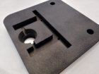
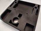
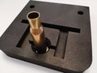
@SGK : I love your enclosure... You say it was custom build... How was it constructed? Is it a sheetmetal laser cutting and bending job? If so, are you willing to share the manufacturing details (CAD drawings and bending schedules).
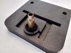
@SGK : There has been a lot of mention that you should NOT drill two holes for the coil, but rather make a slot through the enclosure front panel (if you use a metal enclosure)… You have the 2 holes through the aluminum faceplate... No issues with this?
@SGK ,
@jthor ,
@dulcimer ,
@ernest ,
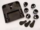
@mktacop : Are you guys willing to share your native files for the 3D printing designs? (should I rather PM to request these)… All of your tables are different, but never the less, all of them nice designs (hope I didn't miss anybody)
Then, in the first part of this 103 page thread, there was an improvement by making use of the adjustable current limiting of the more expensive power suppliers... The idea was to limit the current on smaller cases to move away from the sub 3 second annealing times... This idea then faded away and wasn't referred to later on... Is this still a good idea to implement? The current limit (and setting) could easily be implemented in the Arduino code.
@mktacop : Where did you buy the separate water reservoir / pump? Do you have some details on these please (part numbers) ?
There was also some discussions on the dropping of cartridge through the trap door, but I'm not sure a firm decision was made. Do you leave the case in the coil, power down the coil, then drop the case? Or do you simply drop the case and power down the coils simultaneously?
Is it fine asking all these questions in one post? Or should I rather split them up into several posts?
")
Once I have some answers, I will then start searching for the parts online and start to order them...
THANKS AGAIN for everybody's contributions to this thread