• This Forum is for adults 18 years of age or over. By continuing to use this Forum you are confirming that you are 18 or older. No content shall be viewed by any person under 18 in California.

True Bore Alignment System

I ordered a TBAS Monday night and it’s already here (Thursday afternoon)!

The initial setup portion of the instruction manual discusses using a lesser torque (10-15lbft) for the radial adjustment screws, before a chuck is mounted to the radial plate. After a chuck is mounted, the radial adjustment are torqued to 25-35lbft in use. That makes sense to me; a big beefy chuck bolted on there will greatly stiffen that radial plate, allowing a greater screw torque for a given amount of plate deflection, etc.

The ER-50 chuck I’m waiting for has an 18mm thick mounting flange. This would add some stiffness but not as much as a chuck body’s 2-3” thickness or beam height. Perhaps an upper torque limit of 20-25lbft would be appropriate? Intuitively I wouldn’t think much torque would be required to solidify this system for prevention of chatter with the light cuts I’d typically be taking. But I don’t know that for certain.

Any of you material/stress analysis people want to offer an opinion? I didn’t measure screw thread pitch or take the radial plate off to see what sort of beam dimensions remain after the lightening cuts were made on this V3 version.

I can call or email Nate to get his advice on this but thought others here may be interested in an ER50 setup, and would perhaps chime in.

The weight of this TBAS with a D1-6 mount, but without the ER-50 chuck, feels very similar to my 9” 3-jaw. I use wooden cradles that sit on the carriage arms, positioning the chucks at the right height, to make installing them less strenuous and more controlled. I’ll make one custom for this TBAS as the diameters of the axial & radial plates are different which causes it to sit at an angle in my existing wooden cradles.
 
Last edited:
I ordered a TBAS Monday night and it’s already here (Thursday afternoon)!

The initial setup portion of the instruction manual discusses using a lesser torque (10-15lbft) for the radial adjustment screws, before a chuck is mounted to the radial plate. After a chuck is mounted, the radial adjustment are torqued to 25-35lbft in use. That makes sense to me; a big beefy chuck bolted on there will greatly stiffen that radial plate, allowing a greater screw torque for a given amount of plate deflection, etc.

The ER-50 chuck I’m waiting for has an 18mm thick mounting flange. This would add some stiffness but not as much as a chuck body’s 2-3” thickness or beam height. Perhaps an upper torque limit of 20-25lbft would be appropriate? Intuitively I wouldn’t think much torque would be required to solidify this system for prevention of chatter with the light cuts I’d typically be taking. But I don’t know that for certain.

Any of you material/stress analysis people want to offer an opinion? I didn’t measure screw thread pitch or take the radial plate off to see what sort of beam dimensions remain after the lightening cuts were made on this V3 version.

I can call or email Nate to get his advice on this but thought others here may be interested in an ER50 setup, and would perhaps chime in.

The weight if this TBAS with a D1-6 mount, but without the ER-50 chuck, feels very similar to my 9” 3-jaw. I use wooden cradles that sit on the carriage arms, positioning the chucks at the right height, to make installing them less strenuous and more controlled. I’ll make one custom for this TBAS as the diameters of the axial & radial plates are different which causes it to sit at an angle in my existing wooden cradles.
You are going to be fine, I wouldn't worry about chatter, I have never experienced it on 2 different 1340's and one 1440 lathe, All Asian light duty lathes, Mine has a Gator 6 jaw.
 
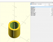
For those with a 3D printer and no CNC, I whipped up a fully parametric tapered collet in OpenSCAD.


Code:
// Tapered Cylinder with Tapered Hole
// All dimensions in inches

// Parameters
outer_diameter = 1.5;      // Outer cylinder diameter
cylinder_length = 1.75;    // Cylinder length
hole_dia_large = 1.25;     // Large end of tapered hole
hole_dia_small = 1.1;      // Small end of tapered hole

// Relief cut parameters
relief_cuts = 4;           // Number of relief cuts
relief_cut_width = 0.04;   // Width of each relief cut (inches)
relief_cut_length = 1.2;   // Length of relief cuts from front (inches)
relief_cut_depth = 0.02;   // How deep cuts go into wall (inches)

// Convert to radius for OpenSCAD
outer_radius = outer_diameter / 2;
hole_radius_large = hole_dia_large / 2;
hole_radius_small = hole_dia_small / 2;

// Create the main cylinder with tapered hole and relief cuts
difference() {
    // Main outer cylinder
    cylinder(h = cylinder_length, r = outer_radius, center = false, $fn = 100);
    
    // Tapered hole - using hull() to create smooth taper between two circles
    hull() {
        // Large end of hole (at z=0)
        translate([0, 0, 0])
            cylinder(h = 0.01, r = hole_radius_large, center = false, $fn = 100);
        
        // Small end of hole (at z=cylinder_length)
        translate([0, 0, cylinder_length - 0.01])
            cylinder(h = 0.01, r = hole_radius_small, center = false, $fn = 100);
    }
    
    // Relief cuts - alternating from front and back
    for (i = [0:relief_cuts-1]) {
        rotate([0, 0, i * (360/relief_cuts)]) {
            translate([outer_radius - relief_cut_depth, -relief_cut_width/2, 0]) {
                if (i % 2 == 0) {
                    // Even numbered cuts start from front (z=0)
                    cube([relief_cut_depth + 0.1, relief_cut_width, relief_cut_length]);
                } else {
                    // Odd numbered cuts start from back (z=cylinder_length)
                    translate([0, 0, cylinder_length - relief_cut_length])
                        cube([relief_cut_depth + 0.1, relief_cut_width, relief_cut_length]);
                }
            }
        }
    }
}

// Optional: Add a visual reference for hole dimensions
// Uncomment the lines below to see the hole profile
/*
color("red", 0.3) {
    hull() {
        translate([0, 0, 0])
            cylinder(h = 0.01, r = hole_radius_large, center = false, $fn = 100);
        translate([0, 0, cylinder_length - 0.01])
            cylinder(h = 0.01, r = hole_radius_small, center = false, $fn = 100);
    }
}
*/


1754138051572.png
 
Code:
// Tapered Cylinder with Tapered Hole
// All dimensions in inches

// Parameters
outer_diameter = 1.5;      // Outer cylinder diameter
cylinder_length = 1.75;    // Cylinder length
hole_dia_large = 1.25;     // Large end of tapered hole
hole_dia_small = 1.1;      // Small end of tapered hole

// Convert to radius for OpenSCAD
outer_radius = outer_diameter / 2;
hole_radius_large = hole_dia_large / 2;
hole_radius_small = hole_dia_small / 2;

// Create the main cylinder with tapered hole
difference() {
    // Main outer cylinder
    cylinder(h = cylinder_length, r = outer_radius, center = false, $fn = 100);
    
    // Tapered hole - using hull() to create smooth taper between two circles
    hull() {
        // Large end of hole (at z=0)
        translate([0, 0, 0])
            cylinder(h = 0.01, r = hole_radius_large, center = false, $fn = 100);
        
        // Small end of hole (at z=cylinder_length)
        translate([0, 0, cylinder_length - 0.01])
            cylinder(h = 0.01, r = hole_radius_small, center = false, $fn = 100);
    }
}

// Optional: Add a visual reference for hole dimensions
// Uncomment the lines below to see the hole profile
/*
color("red", 0.3) {
    hull() {
        translate([0, 0, 0])
            cylinder(h = 0.01, r = hole_radius_large, center = false, $fn = 100);
        translate([0, 0, cylinder_length - 0.01])
            cylinder(h = 0.01, r = hole_radius_small, center = false, $fn = 100);
    }
}
*/


Here's a version without the collet style relief cuts.
 
I picked up a 31mm ER50 collet from Icarbide on ebay for $19. I've bought other stuff from then and know it decent stuff. Another option is Maritool made in the USA for $46.50 and I love their stuff. All my CAT40 toolholders are Maritool. I also need a 32mm or 1 1/4" for the 1.250" barrels I get now and then. I have not got the ER50 collet chuck mounted yet. My day job wont give me a break. Part of owning a shop I guess.
 
I picked up a 31mm ER50 collet from Icarbide on ebay for $19. I've bought other stuff from then and know it decent stuff. Another option is Maritool made in the USA for $46.50 and I love their stuff. All my CAT40 toolholders are Maritool. I also need a 32mm or 1 1/4" for the 1.250" barrels I get now and then. I have not got the ER50 collet chuck mounted yet. My day job wont give me a break. Part of owning a shop I guess.
Myself and a buddy are trying this exact thing with a couple of our lathes... that tapered collet design is a good idea I might have to try that! Almost like making your own barrel bushings for a barrel bise kinda thinking . I will report back should have it up and running on a grizzly 13x40 Smith lathe very soon.

Kasey
 
I really like the idea of 3D printing sleeves for the muzzle end. That will take a lot of time off the job. With all the different taper's I get the double spider set up takes me a lot of fiddling. I got the ER50 collet wrench and its a beast!
 
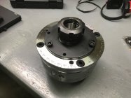
The collet chuck finally arrived today. It comes with a three-hole M8 threaded pattern on a 142mm bolt circle. I opened up the hole diameters and corrected it to fit the M10 bolts on a 140mm bolt circle for the true bore alignment system. I hadn’t anticipated that it would be hardened however. It seemed to machine similar to 1919A4 bolt parts. I could cut it with a carbide end mill but my HSS drill bits didn’t like it. I did get two of the three holes “drilled” with the 0.397” drill bit. But the third would not go. I just clover-leafed it a little with the 3/8” carbide end mill and it will work.

The flange diameter fit the TBAS with a few thousandths clearance.

This chuck is model ER50-D160

The plan is to chamber a barrel using this on Friday.

IMG_3145.jpeg
 
Last edited:
I really like the idea of 3D printing sleeves for the muzzle end. That will take a lot of time off the job. With all the different taper's I get the double spider set up takes me a lot of fiddling. I got the ER50 collet wrench and its a beast!
You weren’t kidding on the wrench being hefty!

And thank you for posting the idea of using an ER-50.
 
That looks great! And you're farther along than me! Paying work comes first but I'll get to it. I knew the Collet chuck was hard. I ran a file across it and didn't leave a scratch. Looking forward to see how you like it. So this is your first time with the TBAS as well right? Me too. Should make it more enjoyable for me.
 
The collet chuck finally arrived today. It comes with a three-hole M8 threaded pattern on a 142mm bolt circle. I opened up the hole diameters and corrected it to fit the M10 bolts on a 140mm bolt circle for the true bore alignment system. I hadn’t anticipated that it would be hardened however. It seemed to machine similar to 1919A4 bolt parts. I could cut it with a carbide end mill but my HSS drill bits didn’t like it. I did get two of the three holes “drilled” with the 0.397” drill bit. But the third would not go. I just clover-leafed it a little with the 3/8” carbide end mill and it will work.

The flange diameter fit the TBAS with a few thousandths clearance.

This chuck is model ER50-D160

The plan is to chamber a barrel using this on Friday.

View attachment 1689627
Hope it goes well, I may setup mine like that too if it works well.
 
I like that a lot more than having a heavy 6 jaw chuck hanging way out there.

Got a 3d printer for your collets?
That was nice of you to share a program for printing them. I don’t have a printer myself but do have a nephew with printers. For Friday’s barrel I had made last week, a bushing out of 6061.

I have no experience turning with a printed bushing. I imagine the surface area being as large as it is, that printed material is rigid enough? What material would you recommend?
 
That looks great! And you're farther along than me! Paying work comes first but I'll get to it. I knew the Collet chuck was hard. I ran a file across it and didn't leave a scratch. Looking forward to see how you like it. So this is your first time with the TBAS as well right? Me too. Should make it more enjoyable for me.
Thanks; I’m just running with your idea! Yes, this will be my first TBAS experience also.

I’d like to be able to support the muzzle end with the outboard spider, and will be directly able to on 28” or longer blanks. Barrels shorter than that won’t reach the spider directly. I had previously been connecting the pressurized fluid system with a hose & hose clamp. I’m thinking now I’ll change over to some threaded pipe connection. Whatever that becomes could be rigid with the barrel and the outboard spider could act on it (with short barrels).

I suppose it could be 1/8NPT but I could do a straighter job threading something with non-tapered thread. Maybe a chunk of an old barrel? Could turn an o-ring recess in a shoulder, to seal against the muzzle end? 1/2-20?
 
Personally I wouldn’t trust a 3D printed collet.

It appears the largest collet you can get is 36mm (1.417). I would personally make up bushings that were 1.417” OD and then taper bored to match the contour and diameter of your barrels. I’d have the bushings bored so they lock on the barrel 1-2” behind the muzzle. Make them out some soft steel or aluminum, tap the bushings on the barrel with a dead blow or make yourself a pusher to tap them on. Then just grab the bushings in the 36mm collet.
 
That was nice of you to share a program for printing them. I don’t have a printer myself but do have a nephew with printers. For Friday’s barrel I had made last week, a bushing out of 6061.

I have no experience turning with a printed bushing. I imagine the surface area being as large as it is, that printed material is rigid enough? What material would you recommend?
100 percent infill will make them more than adequate to clamp onto a barrel.
 
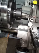
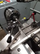
I played with it this evening, dialing in a barrel blank. I used a Gordy rod & bushing, and picked two depths for measurement points, marking them on the rod with blue marker. I’m open to suggestions on picking these points.

As marked, one point is about 1/2” in from end of the blank, the other is about where a 6BRA reamer bushing would land. I tried roughing it in angularly (adjusting the TBAS radial screws) by running the bushing in & out without rotating the spindle for a given axis. But can only get it so close due to about 2 thousandths sag in the rod. I do have some weight hanging on it.
At least that’s what I believe was going on.

At that point I switched to rotating the spindle for measurements and using the axial screws to set the innermost point and the radial screws for the outer. It would be nice to identify the center of the ball that the radial plate pivots on (along the spindle axis I mean). With the Gordy rod a person could pick that location as an initial dial point, thereby eliminating interaction between the two adjustments, correct? Then for a final tweak, check and adjust if necessary, at the throat. Just looking at it, without disassembling and measuring, it appears the ball center is roughly 5 1/2” in from the end of the barrel blank in the below pics.

Edit: see later message post regarding where the pivot center is located.

I set no speed records this time, but left the shop feeling satisfied that precise adjustments are doable. I was impressed with how controllable the angular (TBAS uses the term radial) adjustment is. Moving only 1/10 is not difficult.

Tomorrow I’ll double check the dial-in before proceeding.

Edit to add: Holding the 1/10ths indicator in the tool post is sure nice and solid compared to a typical stand. You can zero the dial w/o deflecting the needle much at all. I’m sure that’s old hat to you professionals, but I found it so satisfying I was compelled to mention it.

IMG_20250828_194807_2.jpegIMG_20250828_194818_3.jpeg
 
Last edited:
Summary of Friday’s chambering experience using the TBAS with ER-50 collet chuck:

Work holding and chatter were of no issue whatsoever. I did no parting and wasn’t hogging off material so can’t comment on how it would have performed under those conditions. Vibration wasn’t perceivable at the 500rpm or less that I was running.

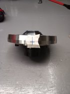
The dialing-in process I’m still learning. It seems the individual adjustments (they use terms axial & radial) behave well enough. It’s not that difficult to move a tenth at a time. But the interaction was causing us extra adjustment iterations. In a previous post I’d guessed at the pivot center being 5 1/2” inward. But after disassembling it I realize I had the wrong mental picture of which direction the spherical shape was pointing (see attached pic). The mark on the piece of tape is a visual guess at the projected center of the sphere.

My BIL & customer if-you-will, working with me yesterday on his barrel, suggested a means of determining the pivot center location. Use the lathe’s DRO to take X & Y measurements along a length of bar stock held in the collet chuck, with the radial plate set at two different anlges. From that, calculate the intersection of the two lines passing through those measured points. I’ll do that one of these next days.

If the axial calibration would be done at this pivot center location, then the radial adjustment wouldn’t interact with it. I believe I’m thinking about this correctly. Counter arguments are encouraged.
.IMG_20250830_100225_0.jpeg
 
Last edited:

Upgrades & Donations

This Forum's expenses are primarily paid by member contributions. You can upgrade your Forum membership in seconds. Gold and Silver members get unlimited FREE classifieds for one year. Gold members can upload custom avatars.


Click Upgrade Membership Button ABOVE to get Gold or Silver Status.

You can also donate any amount, large or small, with the button below. Include your Forum Name in the PayPal Notes field.


To DONATE by CHECK, or make a recurring donation, CLICK HERE to learn how.

Forum statistics

Threads
166,850
Messages
2,223,820
Members
79,918
Latest member
Joe The Licensed Plumber
Back
Top