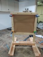
Portable 2 Piece Shot Marker Target Frame
This is a summary of how I built my first, (hopefully my last), target frame for my new Shot Marker system. I am no carpenter and used many ideas from others in this forum. Thanks!
 Objectives:
- Follow the recommendations from Adam McDonald re: construction for accuracy, strong/stiff but lightweight.
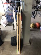
- Designed to be a two part system to allow one (old) person to load/unload and set up
- Largest target area that will allow frame and base to fit flat in bed of my truck
- I knew I wanted to try a stake (the legs), in pocket (mounted on the base) design
Materials Used*
Qty 2 ¾” Birch cabinet plywood 2’x4’ (from Lowe’s, Qty 2 required since I screwed up an early cut….)
Qty 2 8’ 2”x6” white select
Qty 2 8’ 2”x4” white select
Qty 2 3/8-16 Brass threaded insert (Lowe’s, Hillman 880551). Buy a few spares……
Qty 2 3/8-16 bolt, 6” long
Qty 4 3/8-16 nut
Qty 2 3/8” standard flat washer
Qty 2 3/8” fender washer
Kreg pocket screw jig, screws, clamp, etc
*Not a complete list, some misc hardware used that is not shown. This includes construction screws, 90 degree brackets and screws, wire clamps, a simple hinge, etc.
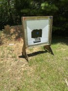
Frame
First I built the actual frame from 4” wide strips of the ¾” plywood using butt joints and pocket screws. The top and bottom are 44” long and the sides are 36” long. This is the largest target area (36’x36”) for a frame and matching base that will lie flat in the bed of my truck. You may need/want a different size. Took extra care to make sure the joints were square and the face of the frame was flat and true. Only enough room for two screws per corner. Did not glue the corner joints but probably should have.
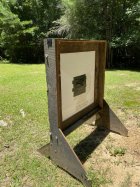
Next I attached two 42” lengths of 2”x4” on the sides as legs. I allowed 12” of leg below the bottom of the frame and I positioned the outside edge of the legs to line up with the outside edge of the frame. These were attached with construction screws.
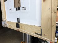
At this point it was apparent that the pocket screws alone were not going to provide the needed strength and rigidity. So I made some corner braces on the back side, see pictures. Not fancy, I used scrap that I had on hand.
I then sanded the sharp edges and corners followed by a quick single coat of Polyurethane to protect the wood in case of an unexpected rain shower.

 Base
Base
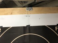
Next I built the base with two on edge 2”x6”s for legs and a single 2”x6” cross piece between them. The cross piece is centered (in both directions) in the sides of the legs to allow for irregular ground between the legs and to provide a mounting surface for the outer pocket sections. Assembled with construction screw and a sturdy 90 degree bracket between the legs and cross piece on the underside. (No picture of those brackets.)
Pockets
The pockets are constructed from short pieces of 2”x4”s and 2”x6”s. The fronts and backs are 2”x4”s and the sides 2”x6”s. The front and two sides of each pocket are 5” high and screwed to each other to make a 3 sided box. The two sides each have a metal 90 bracket for strength. I also used construction screws to attach the outer side of each pocket to it’s leg. This is important since the pockets connect the frame to the base and will have to resist the wind. During assembly of the fixed 3 sided pocket I
used a 1/8” thick shim between the outer edge of the front block and the outer side block to provide the side clearance for the back 2”x4” block.
A taller pocket could be stronger but in my case I needed to load both pieces into my truck and close the tonneau cover. Test fitting them in the truck I ended up with pockets that are 5” off the cross piece of the base. (Note that I did not use screws from the underside of the cross piece to the pocket blocks because I didn’t want to weaken the single cross piece. The pockets are quite sturdy without them if you use the 90 degree metal brackets.)
The fourth side of the pocket (the back) must move freely so it is cut 4 1/2” high. That shim mentioned above provides the side clearance.
Before final assembly of the pockets you will need to test for the right drill bit size for the 3/8” threaded insert pilot hole. These are soft brass and you screw them into the wood with a large flat bladed screwdriver. If your pilot hole is too small the insert won’t go in all the way
and you’ll likely break off one side of the screwdriver slot. If your pilot hole is too large the system will be loose and won’t work. Someone smarter than me can probably call out the correct drill bit size, but I just tested using the spare inserts and scrap wood. I’m still not happy with the size I used so prefer not to share that here. Before I added the pocket hardware I sanded the edges and corners and applied a coat of Polyurethane.
Then I drilled the pilot hole in the center of each front block, screwed in the insert, and drilled a hole in the center of the two back pieces (the back block holes need a slightly loose fit of the 3/8” bolt).
The pockets are completed by threading the 3/8” bolt all the way in (by hand) from the front then adding the rear block over the end of the bolt through its hole. Next, behind the rear block, in this order, add the fender washer, standard washer and 2 nuts on the bolt . Use 2 wrenches to lock the nuts against each other near the end of the bolt. Basically this is a crude wood clamp for the legs. See pictures.
Next I used a jigsaw to cut notches in the bottom of the legs so that they fit over the bolts. The notches should not be excessively wide and just tall enough so the bottom of the legs will rest level on the cross piece of the base (not on the bolt). After a couple of test fits I cut the mouth of the notches a little wider to make it easier to set the frame in place.
To attach the frame to the base you just drop the legs into the pockets and
loosen the two bolts which should pull the back blocks in snug against the back of the legs. I’ve used a rachet/socket or a manual nut driver for tightening and loosening the bolts. I’d be nervous about using anything powered, those brass inserts might not like it.

 Miscellaneous
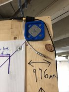
You’ll notice from the pictures that I added a short riser for the Hub. I saw it in other builds and figured it was a good idea. It is hinged and folds down to fit in my truck bed. Used a sliding window lock on the back to lock it upright when in use. I also built a little adapter for a tripod I had on hand to mount the Access Point high and in front of the firing line as Adam suggests. Can’t hurt.
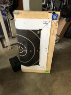
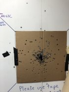
I am using corrugated plastic for the backer. Home Depot sells a large sheet that will yield 2 backers. I mounted small tabs made from the ¾” plywood to screw the backer in place. I haven’t used it with a target yet but know that the 600 yd F-class targets are 37”x37”. So I’ll either trim them to fit directly on the backer or tape them to the face of the frame.
I used Adam’s instructions to measure/mount the microphone bases and calibrate. It all worked the first time. Even with the riser for the Hub I used 2 short and 2 medium mic cables, located them with plastic clamps and wire ties. My plan is to leave them on the frame for easy set up and break down. I’ll carry the 2 long cables as spares.
I have no idea what this little project cost since I had a some of the lumber and hardware on hand. The cabinet grade plywood was fairly expensive but it is stiff/strong and relatively lightweight. The pocket screws are optional if you decide to assemble the frame some other way. That Kreg kit cost about $35 at Lowe’s.
Tips and Improvements
- As I mentioned earlier wood glue could be used in strategic spots. I didn’t because I thought I might have to take it apart and rework it
- I drilled undersized pilot holes for all screws to help prevent splitting
- The pockets need to be monitored for splits and any other problems
- The legs may develop vertical cracks near the top of the notch and split. Thinking about a thin metal plate above the notch on both sides to prevent this, or….
- Replace the 2”x4” legs with legs made from laminating 2 layers of the ¾” plywood. They’d be less likely to split but might not be stiff or strong enough. I have the strips cut and standing by for a possible revision.....
Thanks again to all those that shared their designs, plans and pictures. I studied them multiple times and they were a tremendous help.


")
")