//Chris new code for annealer
// v308
//
//-- Include library
#include <Wire.h>
#include <LiquidCrystal_I2C.h>
//
//-- Assign I/O pins
int irPin = 2; // ir sensor
int trapPin = 8; // trap door relay
int feedPin = 7; // feed motor relay
int ssrPin = 6; // annealer relay
int count = 0; // set case counter to 0
int sensorState = 0, lastState = 0; // sets the ir to open
int Anneal_Step = 0; // program steps
LiquidCrystal_I2C lcd(0x27, 20, 4); // set the LCD address
//
//-- Set up
void setup() {
lcd.begin (); // turns on screen
delay(1000); //delay before the program starts
}
//
//-- Main Program
void loop() {
//-- set the outputs
pinMode(irPin, INPUT_PULLUP);
pinMode(ssrPin, OUTPUT);
pinMode(feedPin, OUTPUT);
pinMode(trapPin, OUTPUT);
feedOffRelay();
trapOffRelay();
ssrOffRelay();
int timerValue = analogRead(A1); //-- rotary timer
int buttonValue = analogRead(A0); //-- push start button
sensorState = digitalRead(irPin); // assigns the ir
float voltage = timerValue * (10.23 / 1023.0);
int a = round(voltage * 10);
float newVoltage = a / 10.0;
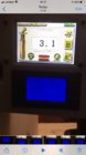
lcd.setCursor(0, 0); lcd.print(" -Set anneal time- ");
lcd.setCursor(0, 1); lcd.print("Timer: "); lcd.print(newVoltage, 1); lcd.print(" sec ");
//-- Begin Anneal Sequence
switch (Anneal_Step) {
//-- Timer set up
case (0):
lcd.setCursor(0, 3); lcd.print(" ...PRESS START... ");
if (buttonValue > 1010) {
lcd.setCursor(0, 3); lcd.print(" ");
Anneal_Step = 1;
break;
}
break;
// -- Turn on feed motor until case is detected by IR
case (1):
feedOnRelay(); // turns on feed motor
if (sensorState == LOW) {
feedOffRelay();
Anneal_Step = 2;
break;
}
break;
//-- Case detected
case (2):
if (sensorState == LOW) {
int b = newVoltage * 1000;
delay(500);
lcd.setCursor(1, 3); lcd.print(" ..Case Detected.. ");
delay(500);
lcd.setCursor(0, 3); lcd.print(" ....ANNEALING....");
ssrOnRelay();
delay(b - 150); // 150 is correction number to get precise ON/OFF timing on pin
ssrOffRelay();
Anneal_Step = 3;
break;
}
break;
//-- Case counter
case (3):
lcd.setCursor(0, 3); lcd.print(" ......DONE......");
lcd.setCursor(0, 2); lcd.print("Count: "); lcd.print(++count, 1); // case counter
Anneal_Step++;
break;
//-- Trap door
case (4):
trapOnRelay(); // turns on trap door
delay(2000);
trapOffRelay(); //turns off relay
lcd.setCursor(0, 3); lcd.print(" ");
delay(2000); // delay before loop starts
lastState = sensorState;
Anneal_Step = 1;
break;
}
}
void feedOnRelay() {
digitalWrite(feedPin, LOW);
}
void feedOffRelay() {
digitalWrite(feedPin, HIGH);
}
void trapOnRelay() {
digitalWrite(trapPin, LOW);
}
void trapOffRelay() {
digitalWrite(trapPin, HIGH);
}
void ssrOnRelay() {
digitalWrite(ssrPin, HIGH);
}
void ssrOffRelay() {
digitalWrite(ssrPin, LOW);
}
//
//-- End code
//


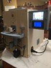
") at the bottom is the actual pump.
at the bottom is the actual pump.")
 .
.
 ....that case is definitely trashed.