• This Forum is for adults 18 years of age or over. By continuing to use this Forum you are confirming that you are 18 or older. No content shall be viewed by any person under 18 in California.

Induction brass annealer redux

I had to do some 300 blackout cases, the coil in straight wind was too tall to get optimal position and heated too much of the case, so I took the bottom coil winding and put it outside the 2nd from bottom winding, (think inverted T shape) it appears to not have changed the coil inductance (in theory it shouldn't), current draw is exactly the same. Still works the same, concentrates the heat in a narrower vertical band. Might experiment with further shapes as I get time.

As a reference for others my unit when in 12.5A current limit does a 223 case in 2.1-3.1 seconds depending on brand. Most are 2.1-2.4, PPU's appear to be quite a bit thicker from shoulder up and take significantly more time.

As of now the Tyco 12v relay has about 12000 cycles on it, no problems.
 
Integrating a fast, high temp, narrow focus IR temp sensor would be neat for those with PLC/Arduino setups but man those things are expensive.

Be cool to just set a target temp and feed cases.
 
I drilled a hole thru my plexiglass base and inserted the sensor inside it close to the case. I had to put a piece of black tubing around it to keep out side lighting since I used clear plexiglass. If I used black I would not have had to do that. I also put an led on the opposite side of the case as a light source. The sensor module has a Digital and Analog output with a sensitivity adjustment pot to control the switching level on the DO. In the pic below the sensor is at the top and led on the bottom.

I used an IR sensor on another project but the beam is too wide to be useful.
https://www.pololu.com/product/2579


annealer.jpg
annealer3.jpg
 
Just another idea. In my Arduino program I started calculating the Joules of energy every 1/10 of a second and totaling it up. For instance if I have 41VDC and on average it pulls 12 Amps for 6 seconds it would have consumed a total of 41*12*6 = 2952 joules. So one could easily just use joules instead of time. I did it but not sure if it gives any advantage or not but it does work. If I heat the same case twice while the case is still hot the amps are going to go up over a constant time and thus the joules go up, but if I keep putting in cold new cases then the joules are more consistent from one case to the next. By switching based on joules then the time gets shorter if the amps go up. I'm not seeing the heat from the induction coil changing it much but I haven't got things setup yet to do a bunch of brass. If it does then it would become an advantage. I was thinking about this because others have been adjusting voltage to keep the amps constant with the better 750W power supply. Of course this reduces the time to anneal because the amps are higher which is the primary advantage.
Another thing I now have for my the Arduino is a flow meter. I used the following from Amazon;
DIGITEN 1/4 Quick Connect 0.3-10L/min Water Hall Effect Flow Sensor Meter
It has nice push-on connectors that work well with the 1/4" poly tubing I am using.
I get about 5.2 gallons per hour through induction coil which is 1/8" tubing. If the flow drops below 4 gph I hold up in the sequence step until a button is pressed.
I was thinking about trying to use an IR temperature sensor to sense the case temperature but the ones I've seen (like the MLX90614) only go up to 716F max and trying to get the sensor focused on the case at the correct spot would be difficult with the induction coil in the way.
 
https://www.omega.com/pptst/OS210-150-300-800.html

Of these you'd want the 801-HT() close focus model 5mm view area @ 100mm distance. Either output style would work with a microcontroller, probably easier to set up the thermocouple output models rather than the 4-20 mA output. 240 mS response is on the slow side, price doubles for < 10 mS. In my mind the faster the response the better but its pricey.

Dream big!
 
For my Arduino parts I'm using the following;

Parts from Amazon;
UNO R3 Atmega328p Arduino, the one I got included the USB cable.
DFRobot Gravity IO Expansion Shield V7.1, makes all the sensors plug and play.


Parts from Robotshop;
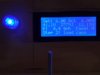
DFRobot I2C/TWI 4x20 LCD Module (RB-Dfr-146)
22cm 4-pin female-female Cable (RB-Dfr-311), got this for the LCD I2C connection
Octopus Voltage Divider Brick (RB-Elf-178), came with cable
Gravity Analog 20A Current Sensor (RB-Dfr-740), came with cable

Parts from Sparkfun;
Illuminated Rotary Encoder (RGB) 10982
Clear Knob for Rotary Encoder 10597
I made my own breakout shield for the rotary encoder. You will need some resistors for the LED's. DFRobot makes a Rotary Encoder but it is not illuminated. DFRobot also has a 10 turn Pot that is nice if you don't want to use an encoder (part#DFR0058, shown in picture below, believe the cable was included, uses a good 10K Bourns POT). Of course it doesn't have the push switch on it so a start push button that is separate will need added.

With this setup the following can be displayed;
Time Setpoint
Time Actual
Volts
Amps
Sequence step discription.

Photo's from my cell so not the best, actually LCD is clear and sharp. I'm also using a wireless Yun module with the Arduino, not necessary but I use this for development and it makes programming easier from across the air. I still am working on assembling the unit, I will need to add a photo sensor or some other sensor to detect if the case is ready. I've left the reading in mSec which it seems to do OK, once in awhile it will overshoot 1 mSec but I'm able to display voltage/amps/and actual time while also having the option to change the setpoint on the fly while the timer is counting up. Eventually I'll probably only show two decimal spaces. I've used about 30% of the Arduino's memory so far. The parts are reasonably priced.


Dear Ottsm,

can you tell me where did you get the clamp and adapter to hook up the copper coil to the vinyl cooling tubes and what specs thx ?
 
Dear Ottsm,

can you tell me where did you get the clamp and adapter to hook up the copper coil to the vinyl cooling tubes and what specs thx ?

You can find these on Amazon and other places. Do a search on amazon for;
"Generic Push in Quick Touch to Connect Reducer Fitting 1/4" OD x 1/8" OD Tube Pneumatic Straight Union Connector"
You can get 1/4" to 1/4" or 1/4" to 1/8".
This is the link;
https://www.amazon.com/gp/product/B01G139HL2/?tag=accuratescom-20
I have used the 1/4 to 1/8 and they work as well but the 1/4" copper tubing help strengthen and support the coil. The ones in the link above are blue in color, the ones in my setup were from something else originally and they are black. We used these at work a lot for pneumatic controlled process equipment. I have had no leaks. Also if you want a flow rate try the following;
https://www.amazon.com/gp/product/B01D44N41U/?tag=accuratescom-20
You will get about 5 pulses per second through the 1/8 induction coil. This is enough for the Arduino to at least sense that the water flow is OK.


Also stumbled onto these at amazon, have not purchased them but they come in a pack of 10 for about the same price;
https://www.amazon.com/dp/B010BY29A8/?tag=accuratescom-20
 
Last edited:
Well I've got my annealing Arduino program almost perfected. I'm using a rotary encoder to set the time and the encoder push button to start the sequence.

The first row of the LCD sets the time to 1/100 of a second, I display in mSec just to see how accurate it is, once in awhile it will overshoot 1mSec. If you press then encoder button while timing the time will stop and sequence will go on to the next step. If the amps go high it will also jump the sequencer to a hold step. The knob LED turns RED while annealing.

The 2nd row shows the volts Joules and amps. The amps are live while annealing but the peak is captured (up arrow displayed when showing peak).

The 3rd row shows the cooling water flow and if a case is loaded or not.

The 4th row shows the sequencer step and what the controller is trying to do. If the flow goes low after an anneal it will also go to a hold step at which point the rotary knob must be pressed to go on.
 

Attachments

  • IMG_2345.JPG
    IMG_2345.JPG
    55.3 KB · Views: 180
can someone help me on the specs for the Solenoid Tubular Pull 12 V DC I tried ordering on www.Jameco.com but they dont carry it anymore is there a subsitute?

thx

Go to digikey.com Go to the solenoids section.Look for a "pull" solenoid (12 volts) that has at least a .5 inch stroke. There are several, see which one meets this requirement and how much you want to pay. Or you could look up, solenoids, on the Jameco web site also. Same spec's
Hope this helps

Gina
 
You can find these on Amazon and other places. Do a search on amazon for;
"Generic Push in Quick Touch to Connect Reducer Fitting 1/4" OD x 1/8" OD Tube Pneumatic Straight Union Connector"
You can get 1/4" to 1/4" or 1/4" to 1/8".
This is the link;
https://www.amazon.com/gp/product/B01G139HL2/?tag=accuratescom-20
I have used the 1/4 to 1/8 and they work as well but the 1/4" copper tubing help strengthen and support the coil. The ones in the link above are blue in color, the ones in my setup were from something else originally and they are black. We used these at work a lot for pneumatic controlled process equipment. I have had no leaks. Also if you want a flow rate try the following;
https://www.amazon.com/gp/product/B01D44N41U/?tag=accuratescom-20
You will get about 5 pulses per second through the 1/8 induction coil. This is enough for the Arduino to at least sense that the water flow is OK.


Also stumbled onto these at amazon, have not purchased them but they come in a pack of 10 for about the same price;
https://www.amazon.com/dp/B010BY29A8/?tag=accuratescom-20
thx for info
 
What cooling pump, radiator, fan is everyone using. I want to mount something more permanent with my current test unit but every cooling setup has it's pros and cons. Would have liked to stick with 1/4 tubing throughout but most are larger.

My setup thus far. Currently using servo but going to try solenoid for ejecting. Still need to get a fan on the induction board also.
 
Just another note, if you want a fiberglass cover for your coil you can get it at Wirecare, FHNG.08NT Ultraflex AWG 8 Natural 10ft, cost is $5.90

https://www.wirecare.com/category/b...-fiberglass-sleeving-8-awg-natural-10-ft-cuts

Wire size 8 AWG is 1/8 tubing. I looked around elsewhere but most was in mm, I'm sure it would probably work as well but the dimensions are not quite the same so it could have been too tight or loose so I didn't want experiment around. The above slides on with a little work and I've done two coils and still have some left over, use heat shrink to dress the ends up. I already had another piece from something else that slides over the 1/4 tubing as well, I use it to insulate from touching the other post where the copper connects to the vinyl.
 
What cooling pump, radiator, fan is everyone using. I want to mount something more permanent with my current test unit but every cooling setup has it's pros and cons. Would have liked to stick with 1/4 tubing throughout but most are larger.

My setup thus far. Currently using servo but going to try solenoid for ejecting. Still need to get a fan on the induction board also.
See the early part of this thread for pump and radiator parts.

Gina
 
Help !!
Have a question why I keep blowing 3a fuse going to 10 on the timer unit ? The solenoid sounds like it clicks then the fuse blows and the timer/12v/48v units still have power ???
Think have all wired to diagram but unsure what I have done wrong . Thanks
 
Help !!
Have a question why I keep blowing 3a fuse going to 10 on the timer unit ? The solenoid sounds like it clicks then the fuse blows and the timer/12v/48v units still have power ???
Think have all wired to diagram but unsure what I have done wrong . Thanks

This has happened on another build awhile ago. Check the operating voltage listed on the contactor relay. Packard C230, (the label on the relay) I'm assuming your line voltage is 110 volt AC.
One other build received a 24 volt AC relay in a 110 volt box, this would blow the fuse. Good thing because it protects the timer contacts, in this situation.
If so, and you ordered it from Amazon, send it back for a replacement.

Hope this helps, let me know

Gina
Thanks for that and the line Voltage is 240 volts and thought I got a 240v contactor but will double check that
 

Upgrades & Donations

This Forum's expenses are primarily paid by member contributions. You can upgrade your Forum membership in seconds. Gold and Silver members get unlimited FREE classifieds for one year. Gold members can upload custom avatars.


Click Upgrade Membership Button ABOVE to get Gold or Silver Status.

You can also donate any amount, large or small, with the button below. Include your Forum Name in the PayPal Notes field.


To DONATE by CHECK, or make a recurring donation, CLICK HERE to learn how.

Forum statistics

Threads
165,544
Messages
2,198,115
Members
78,961
Latest member
Nicklm
Back
Top