Follow along with the video below to see how to install our site as a web app on your home screen.
Note: This feature may not be available in some browsers.
This Forum is for adults 18 years of age or over. By continuing to use this Forum you are confirming that you are 18 or older. No content shall be viewed by any person under 18 in California.
I started making an annealer based on the experiences of a guy on the Stalking Directory forum (UK) who made a very successful one. His was based around a 2K ZVS so I bought all the components I could and started a build. His build used 3/16" copper tube so I did likewise.
I made a coil as he did, But I thought that I could put my cooling tank in the bottom of the PC case I am using and connect the coil to the ZVS using 10mm² cable. I did a couple of test runs and it seemed OK. I have yet to have any success getting any sort of timer in the UK, so it was on the button for testing. Having read the start of this thread and a few pages at the end, it seems everyone is using 1/8" tube and more turns on the coil that I did - mine was about five turns. It did initially seem to work and the cooling kept the coil cool. Then a component on the ZVS blew up. I ordered another but after waiting three weeks from China in turnup smashed to pieces by the courier FFS!
The prime advantage to locating the ZVS in the top of the case is that it gives the fans access to fresh cool air and there is no water to leak into the electronics. I now have to order another ZVS and am wondering if I should use a different one, whether I should give up on my remote power feed?
I'm a half way decent engineer, but my understanding of the theoretical side of electronics is very poor, though my ability to wire stuff is pretty OK.
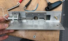
I made a decent job of making the trap door mechanism, though the choice of solenoid is in doubt. I have yet to find a return spring it can pull against. That is work in progress and I am sure I can solve it.
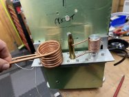
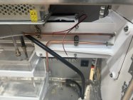
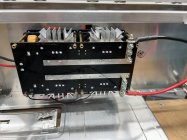
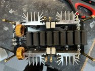
The pic of the inside of the case is with the front panel removed and the dead ZVS which was in the top with its two fan venting to the air. I've shown a pic of the dead ZVS and the bit that went bang was what looks a bit like a five legged transistor/triac sort of semiconductor (far left middle of the photo). Someone suggested it might be a voltage controller? It should be noted that when testing the fans on the ZVS were not operating as I presume they should. I was going to connect them to the 12v power supply long term if that part of the ZVS board was not working.
ANy tips on how to go forward would be appreciated. I have put quite a lot of work into the metal bashing of this project already so moving the ZVS to the middle to facilitate the copper tube directly connecting would be a major ball-ache, but if it's the only was I could do it. Also any ideas as to where to source a timer in the UK? I ordered two from Fruugo and neither arrived, so I have pretty much given up on them after three months!
I did email the guys at MGNZmakes as I was considering their controller board, but got no reply. If they don't reply to messages, made sending money seem unwise.
If the circuit for 2Kw ZVS is basically the same as the 1Kw (just more components) it appears the capacitance is 2.97uf. If you want to run at 100kHz you’d need a .85uH coil. My preference is 1/8” OD tubing.
You should have a fan blowing over the caps.
What power supply are you using for the ZVS?
Keep the cables from ZVS to coil as short as possible.
I agree, keep any cable from ZVS to coil short. I tried going the cable route, but when I rebuilt from the prototype to the final, I got rid of them because they seemed to increase the amount of heat buildup I was getting.
Another thing to consider, is your coil placement. I see you have some kind of fiber board on the inside, but the coil does not seem to be insulated where it goes through the metal mounting surface..make sure it isn't shorting. Which brings up another thought...try to reduce the amount of metal in the vicinity of the coil, it could be interfering with the induction field (maybe).
If the circuit for 2Kw ZVS is basically the same as the 1Kw (just more components) it appears the capacitance is 2.97uf. If you want to run at 100kHz you’d need a .85uH coil. My preference is 1/8” OD tubing.
You should have a fan blowing over the caps.
What power supply are you using for the ZVS?
Keep the cables from ZVS to coil as short as possible.
Sadly there is virtually no documentation with these components from China. It uses a 36volt PSU; I can’t remember the power capacity though.
Following your advice, I’ll make another coil in 1/8” tube and sleeve the ends in 3/16” to fit the connection clamps and the flexi tubing.
The ZVS came with two fans that were supposed to blow over the capacitors but weren’t working.
I’ve been considering using a 16mm battery cable from the coil to the ZVS as that should minimise any losses. Should be more copper in that than even 3/16” copper tube?
I have a friend who is going to see if he can harvest the good components from the courier trashed board and put them on the smoked board. He has some special soldering gear that can do surface mount components. I just have soldering irons!
The front panel is 2mm aluminium with large holes around the exit of the coil tube. The insulator is machined from tufnol. There is no chance of shorting. I’m not an expert on induction, but surely it’s what happens inside the coil that is pertinent; the AMP machine is in a metal case?
True, the AMP case is metal, but to me it looks like the way they insert the case into the machine places the neck/shoulder as low as they deemed necessary considering that they use a different type of induction coil (more like the ferrite type that the Annie Annealer uses if I remember correctly).
The shape of the induction field that our ZVS/coil machines produces is more donut shaped, and the part of the field outside of the coil is just as important as the part inside the coil.
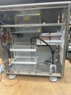
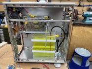
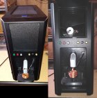
I also used a computer case for my final build, and I cut away as much metal from where the coil protrudes as I could and 3D printed a panel and as much of the case holding shelf below the coil as I could. (see pic below, the top section is an internal case feeder, the bottom half is the coil with the ZVS behind it)
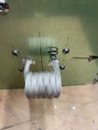
Edit: Your picture of the coil does not give any indication of scale, so just as a reminder, make sure the inside diameter is down around 3/4 inch or so (only needs to be slightly larger than the bases of the cases you will run through it).
On the diameter of the connection cables, bigger is not necesarily better...shorter is better to minimize the resistance.
Also, I believe that the ZVS fans are separately powered and not part of the actual induction circuit...that way they can be turned on or off for cooling as needed. (Edit 2: actually, I just looked closer, and see the fan connectors on the ZVS board, so you would need to disconnect them and wire them separately)
True, the AMP case is metal, but to me it looks like the way they insert the case into the machine places the neck/shoulder as low as they deemed necessary considering that they use a different type of induction coil (more like the ferrite type that the Annie Annealer uses if I remember correctly).
The shape of the induction field that our ZVS/coil machines produces is more donut shaped, and the part of the field outside of the coil is just as important as the part inside the coil.
I also used a computer case for my final build, and I cut away as much metal from where the coil protrudes as I could and 3D printed a panel and as much of the case holding shelf below the coil as I could. (see pic below, the top section is an internal case feeder, the bottom half is the coil with the ZVS behind it)
Edit: Your picture of the coil does not give any indication of scale, so just as a reminder, make sure the inside diameter is down around 3/4 inch or so (only needs to be slightly larger than the bases of the cases you will run through it).
On the diameter of the connection cables, bigger is not necesarily better...shorter is better to minimize the resistance.
Also, I believe that the ZVS fans are separately powered and not part of the actual induction circuit...that way they can be turned on or off for cooling as needed.
I actually wound the coil with a sleeve on it, but it got a little shredded during the process, so all it accomplished was providing spacing between the layers, so I removed it after winding. It also allowed for a tighter winding of the 1/4" tubing.
I also use a pyrex TIG welding sheild where the narrow end fits into the coil and the flared end provides a 'funnel' to guide brass in so it doesn't allow for the brass to short the coil during annealing. I just didn't have it in place when that pic was taken.
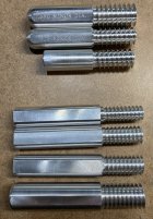
I had a friend, with a cnc lathe, make me some mandrels to wind coils. The bottom 4 are for bare 1/8” tubing and the top 3 are for tubing with sleeving.
High frequency AC current is different than DC. It may be non-intuitive, but thick wires and solid blocks of metal do not necessarily have a lower resistance. If you're interested you can read up on things like "skin effect" and "proximity effect." In these circuits there is a VERY large current oscillating between the coil and the bank of parallel capacitors. Every conductor in or near this “tank circuit" is affected and high current means heat, which is what we want—just not in the electronics.
I would suggest extending the copper tubing along the bottom traces of the PCB. Can you solder components? You can see that the thin PCB traces connect directly to each capacitor and if you solder the (hollow, water filled) copper tubing to these exposed traces you can both lower the resistance and help cool the capacitors. Another thought is to remove every other capacitor and move it to the other side of the PCB. Doing this will allow air from the cooling fan(s) to actually flow between the capacitors and help cool them.
Where the coil connects to the capacitors it looks like it passes through metal. Remove this metal, especially if it is magnetic. Replace it with something non-conductive. Treat everything between the capacitors and coil as part of the coil. Keep the connections between the coil and capacitors as short as possible.
Which component let out its magic smoke? Note that the 4 aluminum heatsinks in your picture may be connected to the tank circuit if they are not properly insulated from the power FETs that they attach to. Even if they are insulated, are the screws magetic? Non-magnetic stainless fasteners will heat up much less.
Make sure your coil is not shorted. A single shorted turn of the coil would be similar to a brass case and will absorb a significant amount of energy. The current draw from the DC power supply should help diagnose things like this.
I had a friend, with a cnc lathe, make me some mandrels to wind coils. The bottom 4 are for bare 1/8” tubing and the top 3 are for tubing with sleeving.
If I have to make a new coil, and it looks as though I should, I was contemplating whether my lathe would have gearing for such a course thread pitch. For 1/8” it would be 6 or maybe 7 TPI. I’ve plenty of HSS to grind a form tool from. No CNC for an old fart like me be fairly easy to make in aluminium. I suspect a 3D printed former would probably work, but I think I’d have more certainly with ally.
I’m still struggling with sourcing a timer. Have any of you guys tried the MGNZ system? I did message them but got no reply.
7 tpi would probably work. I designed my own control board which uses 3 small thumb wheel switches which gave me 10ms resolution. It also provides a choice of timer or “flame sensor” as input, controls drop solenoid, optical detection of case in coil and controls SSR. I still have some un-populated boards.
7 tpi would probably work. I designed my own control board which uses 3 small thumb wheel switches which gave me 10ms resolution. It also provides a choice of timer or “flame sensor” as input, controls drop solenoid, optical detection of case in coil and controls SSR. I still have some un-populated boards.
I have now successfully made a former on my old Harrison M300 centre lathe. No CNC in my corner of Somerset Just waiting for some 1/8" copper tube to be delivered
I did email the guys at MGNZmakes as I was considering their controller board, but got no reply. If they don't reply to messages, made sending money seem unwise.
He could be on vacation, it's summer here. I have no trouble emailing and buying from him. If he is away hunting he could be out of reach electronically
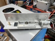
Following the much appreciated words of wisdom on here I have scrapped the previous aluminium front panel. I have now sourced a 1KW ZVS from the evil that is Amazon. I have designed and 3D printed a mounting for it that allows the coil to feed straight onto the board. As suggested I have remade the coil in 1/8" copper which I formed around a mandrel I made on my lathe. I soft soldered to a couple of pieces of 3/16" copper pipe to join to the board. I moved the mounting/connections on the ZVS to keep any potential water leaks away from the electronics. A quick test runs was promising, so the board works.
My case gate was a bloody disaster. I spent loads of wonga having a small neat solenoid shipped from the states and engineered a neat mounting, but it was so gutless that it couldn't pull against the weight of a .338 LapMag case FFS. I then reverted to the monster of a solenoid from Amazon I had initially rejected as being too large. I managed to make it fit and now it could probably pull against a cannon shell.
I mounted one of the fans that came with the, now dead, 2K ZVS in the side of the case and 3D printed a cowl to blow air onto the board on the component side.
I also finally managed to find a Sestos B3S Timer which finally arrived yesterday. I have 3D printed a panel to mount it and the switches to my front panel. I made this panel out of a sign makers composite aluminium faced plastic board which is nice and stiff, but light and easy to cut.
Wiring the Sestos should be straight forward, but programming it scares me - not my forté!!! I want to use it 'one shot' mode which I think means I stick a case in, press start and it heats the case up and spits it out once cooked? I can see that I want to switch the contactor for the ZVS with the A switch and the drop gate solenoid with C. The solenoid says it draws 3 amps - will that be OK with the Sestos or should I stick an extra relay in? I'm a tad confused as to what the Stop and Gate switches do on the Sestos - anyone explain?
I was thinking about having an extra button to open the solenoid gate to eject a case as an override should it be helpful to do so? Thoughts?
Now, THAT's a tank of water. (said like Crocodile Dundee)
Yes, One Shot mode. A is how long you want to cook the case, B is for pause (use 0.00), C is for droping the case (0.5 seconds is usually enough), and D is a pause before returning to A (and stopping in One Shot or repeating in Cycle mode until Stop is pressed). A time of 0.00 is fine in One Shot...in Cycle mode, I use a time sufficient to control machine heat build up (ie 60 seconds between cases to allow for cooling).
The Start, Stop and Gate contacts are wired with the 0V contact and momentary on switches in between. For example, connect a wire from the 0V to the switch and from the switch to the Start contact and when you press the button, the cycle starts. Its the same for the Stop and Gate switches...the Stop obviously stops the timer, and the Gate (when held down) pauses to progress of the timer but without cutting out the relay.
The only use for Gate that I could find, was when determining a run time for a new batch of cases. I set the timer long, then run it with fingers on the case drop button and the Gate button...when I see the case reach the temperature I want, I mash both buttons down. This drops the case and pauses the timer so I can read it and make note of the elapsed time. Then I release both buttons, press the Stop button to turn off the ZVS, and reprogram the timer with the noted time and then re-test another case...fine tune from there.
Here is a link to the programming PDF if you need it:
My annealer seems to have a sudden decay of current, I am running the 1000w
ZVS board and it has at annealed at least 15K cases in the last couple of years.
Voltage is 45v same as always but current for say a 6.5 creedmore case
maxes out at 14A where before it was a 17A. It would get the case necks
to a dim glow in 3.1 seconds it now requires 4.1 seconds to achieve the
same.
Tried 223 cases with the same results, I am thinking the ZVS board is
the issue.
@Ralpharama did you follow up with MGNZ for a reply? I bought 5 shields and arduinos from him just a couple of weeks ago, so there is no issue contacting him, it takes a couple of days sometimes. Maybe your original email went stray?
I was trying to buy 5 premade induction ferrite coils from fluxeon, had initial dialogue from my site enquiry and then nothing when I made further enquiry. Maybe something is lost across the oceans?
I have ended up making my own wound coils and cores from ferrite.
I replaced the 1000W ZVS board with a new unit and my amperage is back to
normal. Upon examination of the old ZVS board the capacitors have swollen probably from the heat even though I have two fans one above and one underneath the board.
I cant complain as I have annealed many thousands of cases.
One thing to note is even though both ZVS boards appear identical the mounting
holes are slightly off.
This Forum's expenses are primarily paid by member contributions. You can upgrade your Forum membership in seconds. Gold and Silver members get unlimited FREE classifieds for one year. Gold members can upload custom avatars.


") Just waiting for some 1/8" copper tube to be delivered
Just waiting for some 1/8" copper tube to be delivered