First, you have to understand how induction heating works.
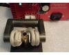
The induction heater contains a high powered oscillator operating at, say, 20 kHZ to 200 kHZ. Its output is an output voltage with high current capacity. This voltage source is connected to a coil commonly called the "work coil." the term "voltage source" must be explained, a voltage source by definition is a low impedance source of a fixed voltage with wide current capacity. When the brass case is inserted into the work coil, the case becomes the secondary of a transformer. By nature of the geometry of the case, this transformer has a "shorted secondary as the secondary is a tube . Some units use a work coil with the case inserted into it, others (like my Annie) use a ferrite core that the work coil is wound around. This core can be square or round, no significant difference. The core has a gap cut into it that the case is inserted into. When the heater is operating, the flux in the core is maximized in the gap due to the permeability difference between ferrite and air. Still, the work coil and the brass case make up a transformer with work coil primary and case secondary. The number of turns in the primary versus the single turn in the secondary (by nature of the "tube" being a single, shorted turn) transforms the voltage in the primary to a lesser voltage on the secondary by the ratio of pri to sec turns. My Annie has 4 turns in the primary so the voltage impressed on the secondary is 1/4 the primary. This turns ratio also increases the current in the secondary to 4 times the current in the primary. So, if the primary has an AC voltage of 100 Volts, the secondary voltage on the case will be 25 Volts. And, for a 1000 Watt unit, the primary can supply 10 Amps (10 Amps times 100 Volts equals 1000 Watts). This 10 amps in the primary is transformed into 40 Amps in the case secondary. The case has a finite resistance so the 40 Amps flowing in the neck of the case produces 1000 Watts (40 Amps times 25 Volts). The actual geometric split of the current in the case is complicated as the resistance of the neck (the hottest part) increases with temp while the case body stays cooler and has less resistance, but the farther you measure from the neck which is in the gap, the less current flows in the case due to spreading resistance from neck to body.
As the secondary is mostly a current source and the primary is driven by a voltage source, the increase in coil resistance makes less effect on secondary current. The internal work coil is cooled to keep it in one piece! The panel connector on my Annie is cooled by holes around it so the internal cooling air driven by a fan passes over it. Without cooling, the connector over-heats and melts the solder in the Litz wire termination which increases resistance even more and takes away power from the case. Cooling minimizes this problem. The AMP has the work coil inside the box so can directly cool it with fans.
See, nothing to it!


") ) kicking over rocks until I find sufficient evidence that either gas or induction is the better method or if perhaps neither has an advantage over the other. Perhaps is comes down to the specifics of the methodology, that is to say the inherently better method is only superior if it is applied in a certain way.
) kicking over rocks until I find sufficient evidence that either gas or induction is the better method or if perhaps neither has an advantage over the other. Perhaps is comes down to the specifics of the methodology, that is to say the inherently better method is only superior if it is applied in a certain way.