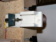
I've been working on this one since early January little by little, its finally at a state I can post about it. I've been looking to build an induction machine for a couple years now. I was searching around on Feebay and stumbled across a 1000w induction board / coil, after watching some videos about it I figured for $35 a guy can't go too wrong. I ended up with a 350W power supply running at 27v to power the board.
The first night of messing with it was exciting, a lot of heat from the board and not a lot of heat to the part. Not exactly what I expected. Not running water through the coil or having a fan on the board made for a lot of heat in no time. The next night I solved the cooling problems. Doing some serious reading on induction and coil theory I made a new coil made from 3/16" copper tube. I couldn't get 1/8" tube locally so I settled with 3/16" to test with. Success. From there I went back to Feebay and ordered a box of 1/8" coil.
With the actual heating part out of the way I needed some control (time). A double relay timer unit with a bit of logic found on Feebay is the ticket. With this I can program the first relay to run the induction board (Amount of time cases get heated) then it switches the second relay to run a solenoid to drop the case out the bottom. I'm still in the process of making the drop mechanism. The other sweet thing about the timer board is it allows for the use of a proximity switch. This will allow me to drop the case into the coil and the induction/case drop cycle will begin once the case is sensed.
Time required is based on case size and coil diameter. Being able to set the timer on the control unit gives exact heating to the case the same every time.
A few pictures as things went along.


A real crappy video of annealing a 338 Lapua case.
Great job. It will interesting to see the finished product.
Very cool ! I just don't know anything about electronics so it's not something I'm going to jump off on.
Nice! I have a pile of parts to build mine, just down the list of stuff to do.
Nice! I have a pile of parts to build mine, just down the list of stuff to do.
How manny watt power supply are you going to run?
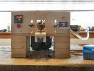
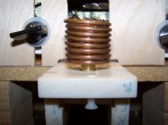
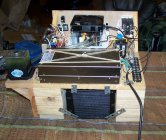
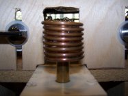
Great minds think a like. The following pictures are an induction annealer I built a few months ago. A fellow forum member named Hollywood and I put our heads together and came up with this design. It was designed as a "concept" build is was not made to look pretty, but it works and works very well. Typically anneal time for a 6XC case is 5.4 seconds. 30-06 is about 5.0. The coil height is adjustable so larger cases can be accommodated (300 win mag, etc) It uses a closed loop water cooling system, run through a radiator/fan.
The power supply is 48 volts rated at 600 watts. The timer is a quad timer. It runs the relay to supply power to the inductor PCB. It than controls the trap door to drop the annealed case and inserts a delay so that a new case can be loaded into the coil, and the cycle restarts.
A power meter was needed to tune the annealing current, too much case in the coil and the power supply will crow bar. Max current with this power supply is 12.5 amps. Also too much current will damage the PCB.
Current is controlled by raising or lowering the coil over the case.
Once everything is set, it is easy to run 8 cases through a minute
Regina
-
040420169.JPG
237.5 KB
· Views: 629
-
04042016b.JPG
210.6 KB
· Views: 626
-
04042016f.jpg
267.9 KB
· Views: 668
-
04042016c.JPG
324 KB
· Views: 519
How manny watt power supply are you going to run?
It's designed to be 1000 watts. If my calcs are correct that should be able to do 308 brass in 2 seconds
It's designed to be 1000 watts. If my calcs are correct that should be able to do 308 brass in 2 seconds
Ahhh, 48 volts at 12.5 amps is 600 watts not 1000. 600 watts max power supply. hence a longer anneal time. And then here is the duty cycle for the PCB. too many too soon, then you over heat.
I wasn't planning on using the eBay induction heater. I am designing a system that can put out 1500 Watts, but the DC is about 50% there. About 80% at 1000 watts. I bought some parts, but just have not had the time to finish the PCB design. Hopefully I'll knock it out this summer. I have not chosen a power supply to run it yet, I might go toroidal transformer and rectifier instead of using a off the shelf switching power supply. If I do use an off the shelf one of the 48 volt acme power supplies will most likely be used.
These machines are great - what frequency are y'all running thru your induction coils? It seems like this would be a great application for an Arduino, to control the annealing time and also check for things like coil temp or overcurrent. It could also control a drop solenoid as mentioned above, which might or might not be necessary if you're hand feeding cases.
I'm going to control mine with a Texas instruments msp430 or C2k. It's what is going to drive the electronics. Much much easier that way. Then I can just adjust everything as I need to. Looks like 100-400khz is ideal for brass.
Great minds think a like. The following pictures are an induction annealer I built a few months ago. A fellow forum member named Hollywood and I put our heads together and came up with this design. It was designed as a "concept" build is was not made to look pretty, but it works and works very well. Typically anneal time for a 6XC case is 5.4 seconds. 30-06 is about 5.0. The coil height is adjustable so larger cases can be accommodated (300 win mag, etc) It uses a closed loop water cooling system, run through a radiator/fan.
The power supply is 48 volts rated at 600 watts. The timer is a quad timer. It runs the relay to supply power to the inductor PCB. It than controls the trap door to drop the annealed case and inserts a delay so that a new case can be loaded into the coil, and the cycle restarts.
A power meter was needed to tune the annealing current, too much case in the coil and the power supply will crow bar. Max current with this power supply is 12.5 amps. Also too much current will damage the PCB.
Current is controlled by raising or lowering the coil over the case.
Once everything is set, it is easy to run 8 cases through a minute
Regina
Looks like we are using the same induction board. Not knowing what I was getting into I went with the 350w power supply due to cost. Now that I know the board works well, and even better knowing what you are running it at I'm going to up the juice. Your machine looks good, functionality is key. What did you use for a solenoid to drop the case? I have a few electromagnetic solenoids I'm messing around with. I'm just at the point I want to get the mechanics sorted out. The electrical is pretty much wrapped up at this point, which is an accomplishment in its self. This stuff is fun.
Missed,
What are you using as your design reference - ie. info on how much power, frequency, coil size, etc? Seems like it shouldn't take much more than a few hundred watts to anneal a case neck, considering how thin that metal is.
I calculated the theoretical power from
specific heat of brass, temperature rise from 70-750 degrees, mass of desired heating section of 308 brass.
I found that times in the 4-5 second range the MATLAB thermal conductivity simulation shows the upper section of the body getting into the 500's around the 4 second mark. 2 seconds was showing the neck, shoulder and about 1/4" down the shoulder/body junction reaching the anneal temp and the lower half of the body not reaching 400 degrees. Granted these are simulations and I was simulating the heat source right at the neck junction, how focused it really will be in real life I have yet to determine.
Yes lower wattage will still anneal it. I want to make sure I can hit it quickly to anneal the desired area and be done. Limiting the amount of heat that travels down the body, I did try to contact someone that I know that makes custom controls and I know they have built a complete ammo plant from the raw brass stock to completed ammo but he did not specifically work on the annealing section and they are treating it like super top secret squirrel stuff, so I was not able to get any information on there annealer design. All I know about it is that it is very impressive. They even had the sections broken up into teams and there are only a couple people that have the knowledge of point a to z, most only have a small slice of the project.
I found the induction frequencies in a metallurgy text book that I have. Lower frequencies for thicker metals, higher frequencies for thinner metals.
I have not gotten to coil size. From the research I have done so far it is kinda voodoo science, try and try again. I do have some 5mm copper tube and I was thinking 3 wraps and run up to the heat exchanger (small transmission cooler that I have) and pump through it with a fan on the Hx. It will be about June before I can really get back on it. Gotta get the powder dispenser 100% first along with a few more irons in the fire that are hotter.
Looks like we are using the same induction board. Not knowing what I was getting into I went with the 350w power supply due to cost. Now that I know the board works well, and even better knowing what you are running it at I'm going to up the juice. Your machine looks good, functionality is key. What did you use for a solenoid to drop the case? I have a few electromagnetic solenoids I'm messing around with. I'm just at the point I want to get the mechanics sorted out. The electrical is pretty much wrapped up at this point, which is an accomplishment in its self. This stuff is fun.
It's just a 12 volt solenoid, same 12 volt PS I use to run the water/cooling pump. Timer activates it for .3 seconds. Enough time for the case to fall through the trap door. Got it through Jamesco Electronics
www.jamesco.com.
Costs about 8 bucks.
-
04052016g.JPG
237 KB
· Views: 280
-
top of trap B.JPG
135.9 KB
· Views: 241
It is fun. Hollywood did the real work on figuring out the coil size, and coming up with the idea of the water cooling. I just added the electronics (which was my profession/retired now)
Good luck on your build and design.
Wow Matlab sim... that's what I call forethought. Yeah inductive heating seems like one of those industrial "secrets" where if you don't do it, you don't need to know about it - or rather there's not many people who care to write a book about it at the end of the work day.
The cutting edge heaters use a feedback system to optimize their resonant frequency, which increases the efficiency of the system. Not sure if your friends use that, but it seems like it'd be overkill for neck area annealing.
This has been posted before but thought I'd throw my comments in again.
http://forum.accurateshooter.com/threads/induction-annealer-almost-done.3857709/
I designed a PCB for the auxiliary controls (case sensing, turning the unit on/off, solenoid operation & timer). I used a PIC and believe I may have a couple extra boards. Used optical sensing for the presence of the case. When that is tripped the unit turns on for the time displayed on the pushwheel switch. Decimal point is missing but it's after the first digit on the left. So, 10ms resolution. After the unit turns off the solenoid is activated and is left on for 100ms after the case clears the sensor. Could have used a fixed amount of time but thought I'd make it dynamic. Basically, I did it because I could.
I used 1/8" refrigeration tubing and wound them around mandrels I had a friend make on his Haas. I wanted mandrels because I didn't want the tubing to kink. I use different diameters for different sized cases. Figured the smaller the ID the better the magnetic coupling.
I added the water cooling after I found the coil getting too hot after a dozen or so cases. The tank doesn't need to be as big as it is.
I bread-boarded for a year or so with so-so results. After 50 years in the analog IC design business, it isn't as much fun anymore!
I went for the Annie and was patient through their intro to production and now have a very nice annealer.
You may want to check out their flux concentrator. It is simply a pair of C cores with one cut out just over the width of the largest case you will use. They also use some fat Litz wire to lower copper losses/skin effect. I tried using #4 solid wire and actually got better results. Either one will work. Mine use 4 turns, arranged so 2 are over each "end" of the core. Don't forget to flow water over while cutting the ferrite with a diamond Dremel tool blade. And, annealing is quick!
Upwards of 5 seconds per case for about 10-20 minutes for 100 cases.
One thing I did not mention on the annealer I built. Total cost was less than $400. All parts were off the shelf (hardware store or Jamesco Electronics) or ordered from Amazon. Only two items had to be home made. One was the coil (from Hollywood). The other was the trap door assembly. If you've got a small router table and a drill press, it's not a problem.
Trap door material is "Corion" and is a counter top material. Be sure to use nylon screws.
Gina


