• This Forum is for adults 18 years of age or over. By continuing to use this Forum you are confirming that you are 18 or older. No content shall be viewed by any person under 18 in California.

Big Align Boring Job On A Harbor Tug

jackieschmidt

Gold $$ Contributor
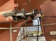
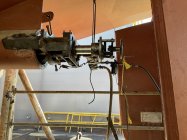
I am at Sterling Shipyard in Port Neches Texas this week align boring the Stern Tubes on a 5000 HP Harbor Tug.

They have been having problems, and finally determined that the Stern Tube Bearing and Inboard Shaft Seal are not where they are supposed to be.

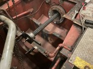
Working off of a laser, we are align boringp the Stern Tube so they will be in alignment with the reduction gear and strut.

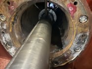
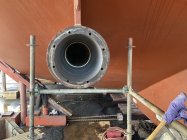
The vessel has eleven inch diameter shafts. We are boring approx 1/2 inch to the side out to make rom for a pressed in sleeve that the bearing will mount in. The finished bore with 3 steps is a nominal 13 3/4 inches diameter.

It’s about a four day job. We finishedIMG_2749.jpegIMG_2748.jpeg the Port Side yesterday evening and are now set up on the Starboard side.
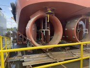
Here are some picIMG_2751.jpegIMG_2753.jpegIMG_2750.jpeg
 
Last edited:
I spent 17 years at EMD, mainly in the engine divisions. The marine engines were cool. Lots of different parts from the locomotive engines.
This vessel originally had regular blown 16-645’s, they have upgraded them to the intercooled turbo set up mainly for emissions, they could easily ring 3000 HP out of them.

I have aligned many of them through the years, checking crank deflection, and drilling the foundations. It always amazed me how these huge engines just sat on those four little mounting pads.

We always put body fit bolts in the rear, but clearance holes in the front feet so the engine can grow as it heats up and not throw the main bearings in a bind.
 
The locomotive underframes were built with a camber. A portable mill was set on them to mill the pads for the engine, alternator, and air compressor. The mill was heavy enough to simulate the added weight as the addition of everything took a lot of the camber out. No telling how much everything flexed going down the tracks.
 
I spent 17 years at EMD, mainly in the engine divisions. The marine engines were cool. Lots of different parts from the locomotive engines.
Back then you you would have never guessed a new 710 EMD would have electrical wires inside it and a computer hooked to it.. To me was an amazing engine for parts that would interchange between an 8 cylinder up to a 20 cylinder engine.
 
The locomotive underframes were built with a camber. A portable mill was set on them to mill the pads for the engine, alternator, and air compressor. The mill was heavy enough to simulate the added weight as the addition of everything took a lot of the camber out. No telling how much everything flexed going down the tracks.
With boats, it’s a compromise. Since you are running on an irregular ever changing surface, someone has to decide how the alignments will be done. This includes how much ballast in the tanks and how much fuel load.
It’s really amazing that it all works as well as it does, considering some of the conditions these vessels have to operate in.
Back then you you would have never guessed a new 710 EMD would have electrical wires inside it and a computer hooked to it.. To me was an amazing engine for parts that would interchange between an 8 cylinder up to a 20 cylinder engine.
Heck, from the outside, the old 567 EMD looks just about the same as the 645, and the 645 looks about the same as a 710.

In years past, I knew of companies who put 645 cylinder and head assembly’s on old 567 blocks.

From what I know, the crank journals and rod throws are pretty much the same. A 645 is a bored out 567, and a 710 is a stroked out 645.

I know one thing. In a big Tug, those big EMD’s sure sound awesome when they rev up under load, especially the Turbo ones. When that Turbo starts spooling up, you can just hear the horses getting ready to stampede.
I think they could record that sound and sell it.:cool:
 
Last edited:
One of the things a railroad could do when buying new locomotives, was use things like the crankshaft from a tradein. The journals are all the same in all three engines. Old cranks would come in, get inspected, chrome plated back to size if needed. It was finally decided around 1980, that cranks that had been made in the late 40s or 50s, were not up to the new stresses.
 
One of the foundries I worked in made cylinder sleeves for the GM EMD division in the 70's.
In 1983 I had a job offer from the Cooper Energy foundry in Grove City PA. where some of the locomotive blocks were cast.
 
The big EMD turbocharged engines have an interesting feature most people probably don't know about. These are 2 cycle engines and need positve intake pressure to run. To get this, the turbo is engine driven through a gear train at slow speed or light load. Once throttled up, which is done by injecting more fuel, the heat and flow of the exhaust increases. There is a clutch that releases at some point letting the turbo continue to spool up. The locomotive engines use a roller clutch, a lot of the marine engines use a ratchet clutch.
 

Upgrades & Donations

This Forum's expenses are primarily paid by member contributions. You can upgrade your Forum membership in seconds. Gold and Silver members get unlimited FREE classifieds for one year. Gold members can upload custom avatars.


Click Upgrade Membership Button ABOVE to get Gold or Silver Status.

You can also donate any amount, large or small, with the button below. Include your Forum Name in the PayPal Notes field.


To DONATE by CHECK, or make a recurring donation, CLICK HERE to learn how.

Forum statistics

Threads
165,885
Messages
2,205,484
Members
79,189
Latest member
Kydama1337
Back
Top