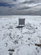
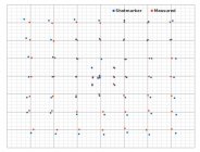
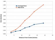
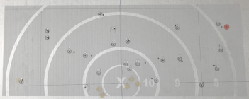
I want to present the analysis I performed on the accuracy of my Shotmarker setup. I wanted to evaluate, with good due diligence on target preparation, how much error was observed across the area of the target during normal outdoor shooting conditions. A little groundwork first: I have a frame that is 44 inches square, built with 1x2 pine and choroplast backer. Everything is glued together and squared up. I have 550-cord guylines attached to the top corners of the frame so that I can anchor it in place with stakes. This whole design was meant to be light, but square and rigid when fully anchored. I've been using it for about a year now and it has been holding up well!
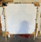
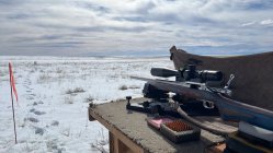
The Pawnee Grasslands where I shoot do not allow any motorized vehicles off of the established roads, so the target must be carried into position on foot. This area also gets significant wind and has been a challenging but instructive place to load develop and practice. Mirage is commonplace, and apart from distorting the aim point, I have come to appreciate it for helping me understand what the conditions are doing.
I prepped a large piece of butcher paper with meticulously drawn lines on 5 inch spacing, creating a 30” by 30” grid and 49 nodes, or aim-points. The goal was to shoot at each node and get a regular array of bullet holes to measure and compare to the Shotmarker recorded positions. All lines were checked multiple times for square with different size 3-4-5 triangle measurements as well as measuring relative to each other in x and y. 6” calipers and a 14” engineer’s scale were used for all measuring, both now and for bullet holes later. No line measured more than 0.005” out of position. These lines will be used to check bullet position from multiple directions to help reduce the error. Trying to measure a position some 22 inches from the origin is not trivial. The Shotmarker defines the origin at the center of the 4 sensor towers and I inked the x-y axis to make them more visible and permanent. 1” dots were stuck to each intersection for high-visibility aim points.
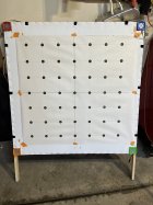
Note the hash marks on the choroplast to help me align the target. I wasn’t unduly concerned about absolute true center, because we will use all the shots to find an x and y calibration value that minimizes the average error.

The Pawnee Grasslands where I shoot do not allow any motorized vehicles off of the established roads, so the target must be carried into position on foot. This area also gets significant wind and has been a challenging but instructive place to load develop and practice. Mirage is commonplace, and apart from distorting the aim point, I have come to appreciate it for helping me understand what the conditions are doing.
I prepped a large piece of butcher paper with meticulously drawn lines on 5 inch spacing, creating a 30” by 30” grid and 49 nodes, or aim-points. The goal was to shoot at each node and get a regular array of bullet holes to measure and compare to the Shotmarker recorded positions. All lines were checked multiple times for square with different size 3-4-5 triangle measurements as well as measuring relative to each other in x and y. 6” calipers and a 14” engineer’s scale were used for all measuring, both now and for bullet holes later. No line measured more than 0.005” out of position. These lines will be used to check bullet position from multiple directions to help reduce the error. Trying to measure a position some 22 inches from the origin is not trivial. The Shotmarker defines the origin at the center of the 4 sensor towers and I inked the x-y axis to make them more visible and permanent. 1” dots were stuck to each intersection for high-visibility aim points.

Note the hash marks on the choroplast to help me align the target. I wasn’t unduly concerned about absolute true center, because we will use all the shots to find an x and y calibration value that minimizes the average error.
Last edited:


