Follow along with the video below to see how to install our site as a web app on your home screen.
Note: This feature may not be available in some browsers.
This Forum is for adults 18 years of age or over. By continuing to use this Forum you are confirming that you are 18 or older. No content shall be viewed by any person under 18 in California.
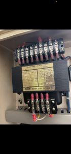
Recently bought an older Bridgeport Romi 13-5 lathe and got it wired in. Noticed after a month or so after doing a project that the transformer inside the lathe was pretty hot and looks like the wiring is being affected by the heat.
From pictures I took before I wired it in, I noticed the wires looked the same as they do right now. So I assume it was an issue from previous owner, not something I caused. Lathe is running fine currently, thinking I should get another transformer to replace it though. Just curious what people are finding from their transformers in their lathes? Been trying to get ahold of technicians to help with no luck.
Is a hot lathe transformer normal?
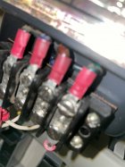
Are the wires showing deterioration due to the heat mixed with how old it is?
With not using the coolant pump, is having it wired in causing any issues?
Curious if anybody knows any good transformers that would be a relatively easy swap, as I’m not an electrician by trade but understand a little bit of it.
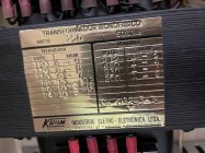
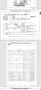
Wiring diagram showing needs of 115v and 28v from transformer and the motor of my lathe is a 200v motor and being supplied with 208v based off name plate as pictured.
I'm not sure you have a problem. Transformers do get warm/hot. All the discoloration appears to be above the transformer. Heat rises. But this just an opinion.
I'm not sure you have a problem. Transformers do get warm/hot. All the discoloration appears to be above the transformer. Heat rises. But this just an opinion.
I appreciate the response and insight. Been scratching my head about it thinking the same thing. Just wanted to get some more opinions from people who are more knowledgeable than I am on the matter.
I appreciate the response and insight. Been scratching my head about it thinking the same thing. Just wanted to get some more opinions from people who are more knowledgeable than I am on the matter.
Maybe remount it outside the cabinet and use a fan like mentioned, outside the cabinet would be a benefit to the wiring due to the heat and if ever the smoke wants to get out the transformer too bad (fire) it will probably do less damage to the lathe control electronics and motor. Use wire one gauge up that it is currently if you choose the move it as the runs will be longer which could be a problem if it was designed close to spec.
Or do the smart thing and just ignore what I said.
What is your source for 3 phase? The voltage on each leg may be different. Make sure your input voltage to the transformer is correct. You may need to put it on a different leg.
What is your source for 3 phase? The voltage on each leg may be different. Make sure your input voltage to the transformer is correct. You may need to put it on a different leg.
The source is a VFD. Which is programmed with all the parameters of the plate on the lathe. The VFD is then wired into the disconnect of the lathe. The VFD is never touched when operating and is only supplying a steady supply of what the lathe says it wants on the plate to mimic regular 3 phase power to continue to utilize the factory controls on the lathe without having to gut and rewire. The VFD is always fully engaged before I turn the disconnect on to prevent the ramp up messing with the electronics. So the lathe is never seeing anything other than a regular 3 phase load it would regularly see if it was wired into regular 3 phase. I talked to a few VFD manufacturers and lathe companies when wiring this in about if it’s okay to wire it this way and they agreed with the thought that a load is a load and as long as I’m not trying to vary the frequency to get variable speed it won’t matter. The lathe can’t tell at that point if it’s 3 phase from the breaker or from 3 feet away from the VFD.
The source is a VFD. Which is programmed with all the parameters of the plate on the lathe. The VFD is then wired into the disconnect of the lathe. The VFD is never touched when operating and is only supplying a steady supply of what the lathe says it wants on the plate to mimic regular 3 phase power to continue to utilize the factory controls on the lathe without having to gut and rewire. The VFD is always fully engaged before I turn the disconnect on to prevent the ramp up messing with the electronics. So the lathe is never seeing anything other than a regular 3 phase load it would regularly see if it was wired into regular 3 phase. I talked to a few VFD manufacturers and lathe companies when wiring this in about if it’s okay to wire it this way and they agreed with the thought that a load is a load and as long as I’m not trying to vary the frequency to get variable speed it won’t matter. The lathe can’t tell at that point if it’s 3 phase from the breaker or from 3 feet away from the VFD.
I'm by no means an expert on VFD's, But normally they are not used with the factory electrical components. That's bad juju. The only thing normally used on the lathe is the apron switch, All other controls are abandoned. I think this is where your problem lies.
I would figure it out soon because that particular transformer is expensive and may be hard to find, I went through this on my 3 phase Gear head mill.
Check with a guy named Mark on the hobby machinist forum who's handle is mksj , He knows more about VFD's than most people do. A tech you call from a vfd company is not going to know what he knows and most people buying vfd's from those companies are not using them on a lathe, They are for machines in mfg plants etc.
I'm by no means an expert on VFD's, But normally they are not used with the factory electrical components. That's bad juju. The only thing normally used on the lathe is the apron switch, All other controls are abandoned. I think this is where your problem lies.
I would figure it out soon because that particular transformer is expensive and may be hard to find, I went through this on my 3 phase Gear head mill.
I’m by no means an expert either, but a load should be a load, right? If 3 phase is coming from the grid at 208 volts vs coming from the VFD at 208 volts how can the machine tell the difference? Where I figured the bad juju comes from is when a person is trying to get variable speed and is adjusting the frequency instead of leaving it set at 60hz at all times and using the VFD just as a phase converter. I could definitely see a varying frequency giving a transformer a bad time and start burning some stuff but with everything programmed and left the way that the machine plate wants it, I don’t understand how the VFD in this state could be ruining the electrical components. This is how VFD manufacturers had made it sound also when I talked to them when figuring out how I wanted to wire it in as well. If I’m mistaken please correct me, because as I said before I’m by no means an expert. But would like to understand why this way shouldn’t work either.
I’m by no means an expert either, but a load should be a load, right? If 3 phase is coming from the grid at 208 volts vs coming from the VFD at 208 volts how can the machine tell the difference? Where I figured the bad juju comes from is when a person is trying to get variable speed and is adjusting the frequency instead of leaving it set at 60hz at all times and using the VFD just as a phase converter. I could definitely see a varying frequency giving a transformer a bad time and start burning some stuff but with everything programmed and left the way that the machine plate wants it, I don’t understand how the VFD in this state could be ruining the electrical components. This is how VFD manufacturers had made it sound also when I talked to them when figuring out how I wanted to wire it in as well. If I’m mistaken please correct me, because as I said before I’m by no means an expert. But would like to understand why this way shouldn’t work either.
If I was you, I would run your machine on a rotary converter. You can build one for about what it cost you to buy your vfd assuming you bought a good one and not a chinese one.
VFD's and static converters don't give you a true 3 phase power. The control panels on the lathe do all kinds of weird stuff when you try running a vfd through them.
The source is a VFD. Which is programmed with all the parameters of the plate on the lathe. The VFD is then wired into the disconnect of the lathe. The VFD is never touched when operating and is only supplying a steady supply of what the lathe says it wants on the plate to mimic regular 3 phase power to continue to utilize the factory controls on the lathe without having to gut and rewire. The VFD is always fully engaged before I turn the disconnect on to prevent the ramp up messing with the electronics. So the lathe is never seeing anything other than a regular 3 phase load it would regularly see if it was wired into regular 3 phase. I talked to a few VFD manufacturers and lathe companies when wiring this in about if it’s okay to wire it this way and they agreed with the thought that a load is a load and as long as I’m not trying to vary the frequency to get variable speed it won’t matter. The lathe can’t tell at that point if it’s 3 phase from the breaker or from 3 feet away from the VFD.
I sell VFDs for a living and I have never heard of someone feeding the output into a transformer. I am not saying it won't work but here are some things to consider.
The output from a VFD is not a clean sine wave. It is a pulse width modulated square wave that is trying to emulate a sine wave. The peak voltage levels of the square wave out of your VFD are probably higher than the RMS peak wave that the transformer is rated for.
I say probably, because I am making the assumption that the input to your VFD is 230V single phase, and you are using it to convert to three phase. When you do it that way, the VFD converts the input voltage to 320 VDC, and the output is pumping all of that into your 230V transformer at a high frequency. The transformer is designed for a 50/60 Hz sine wave input. When pushing the high frequency into the transformer, you are encountering efficiency loss, which is turned into heat.
The transformer may last forever but my guess is the insulation will eventually breakdown and it will fail.
The transformer is probably a single phase unit. You could remove the VFD connection from the input of the transformer and bypass the VFD by wiring the 230VAC directly to it, fusing and using a disconnect as needed.
The transformer is usually wired off of one leg (115) and then gives 24 volts. At least that's what I have encountered on lathes and mills that are 3 phase and have magnetic contactor setups.
The transformer is usually wired off of one leg (115) and then gives 24 volts. At least that's what I have encountered on lathes and mills that are 3 phase and have magnetic contactor setups.
Like others have stated the waveform from the vfd is not a sine wave and it can cause heating issues with transformers. When we consulted on a machine we were advised to run a much larger transformer than originally supplied due to the heating issues.
It shouldn’t be that hard to source a larger transformer or even two transformers to cover the single phase 220V input and 115V and 28V outputs.
BTW the schematic shows the transformer is single phase using only two legs of incoming power. Its purpose is to step down 220V input to 115V for the controls and 28V for the spindle brake.
Thank you for clarification. My supply power to my VFD is 240 single phase. So could a guy wire the VFD into the motor, then upstream of the VFD put a switch that supplies the 240 single directly into the transformer? Then a guy can turn the power off and on to the transformer whenever he’s turning on and off power to the motor manually.
Don’t know if it matters but that schematic is also showing it’s for a 230volt model lathe and mine is a 200/208. The lathe didn’t come with the manual so I found one online for it but it’s just printed for the 230.
This Forum's expenses are primarily paid by member contributions. You can upgrade your Forum membership in seconds. Gold and Silver members get unlimited FREE classifieds for one year. Gold members can upload custom avatars.