• This Forum is for adults 18 years of age or over. By continuing to use this Forum you are confirming that you are 18 or older. No content shall be viewed by any person under 18 in California.

Induction brass annealer redux

Hi Gina. I have used a NO NPN inductive sensor with 8mm detecting range from EBay ,

DC 6-36V Wire Inductive Proximity Sensor Detection Switch NPN LJ18A3-8-Z/BX - $AU17.52


but I think this compacitive sensor with 10mm detection range (from EBay) would be better.

DC 6-36V NPN NO 3-Wire Capacitive Proximity Sensor Switch 10mm LJC18A3-B-Z / BX - $AU18.46


What I would be after with the second one is particularly the 10mm detection range, as I have had the very occasional 223 case slip past the sensor without activating it. Either inductive or capacitive is fine but NOT magnetic, as our brass cases have zero magnetic qualities and will not energise the sensor. Inductive sense metal objects and capacitive sense any object, so they will both work quite well with brass cases.

Whatever you get, read the specifications very carefully. It needs to be Normally Open (NO for the benefit of other readers) so the passing case will close it and activate the signal. Also, preference is for the longest detection range you can find - 4mm is a waste of time, my current 8mm is good 99% of the time, but I think 10mm would be 100% reliable.

With the part number LJ18A3-8-Z/BX the -8- part usually indicates detection range in this case 8mm, so -4- would be 4mm and so on. That seems to work most of the time. But then the capacitive one listed above has -B- and is 10mm. What that means in this item is anyone's guess.

You then need to work out how you are going to get the cases to consistently pass and activate the sensor. As mentioned above I used a funnel and cut the sensor into the back of the neck of it, but you could just as easily have the cases roll across the face of the sensor. The possibilities are endless.

Bruce

Thank you for the information. Checked on line and there are a number of sources for the sensor. NOW it is just a matter of "doing it" I guess if I was to add auto-feed it would be good.
But for the most part I'm annealing 100- 200 cases a month, and I have the timing and rhythm down so it only takes about 15 minutes to do 100 cases.
BUT... I will think about it :rolleyes:
Again... thank you for the info and adding your idea's and sharing.
Gina
 
What's funny, @Gina1 , is that my basic annealer works perfectly - and I agree, it's fast and easy enough that I really have no need to automate the thing. I'm updating mine to Arduino control as an excuse to learn about that stuff, not because it needs it. I enjoyed building the first rev of mine so much, I figured why not take on another project with it - and it's been super fun, so far! I mean, especially since we're all stuck at home for a little while longer o_O
 
In the same way, I ended with two annealers. And to be fair to them, I divide the workload by caliber.

Ever think about selling one ? Every now and them I've been asked to build one for sale. Being retired I like my time being my own so I did not want the hassle.
The basic unit is easy to build (especially after getting the bugs out, design wise) and I think it would sell like hot cakes.
 
Ever think about selling one ? Every now and them I've been asked to build one for sale. Being retired I like my time being my own so I did not want the hassle.
The basic unit is easy to build (especially after getting the bugs out, design wise) and I think it would sell like hot cakes.
Standardizing a basic "ikea" like build, with various wires to length, terminals attached, holes drilled, instructions, etc, might be an idea for an "Assemble-it-yourself" item.
 
Gina,
Being retired, I put a lot of bells and whistles in the annealers, which make them no cheap and would expose me to continued technical support. I would like to enjoy my retirement with some nostalgic electrical engineering activity. A third machine might be on the way;)
 
Firstly thanks to Gina for initiating this post and the healthy, lively and creative responses it has generated.

After finishing my GinaErick annealer I’m sharing my experience for the benefit of other to learn as I learnt from the many posts here.
In no particular order:
- Using a cheap eBay LC meter (LC100A) the original 1000W induction coil measured 1.5micro henry, the 8 turn 1.125 inner diameter 3mm replacement coil measured 1.1micro henry.

- With no load the induction board draws 9.5A (much higher than expected), with full load my PSU gives 11.1A and unfortunately that seems to be its maximum regulated current despite being advertised as 12.5A. The 9.5A might be due to the coil being lower inductance than the original, I will do further testing on the next one I build.

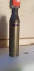
- Not all brass is created equal. ADI brass was annealed for 9.2secs and tempilaq melts 1mm below the shoulder, it has been through the annealer 20 times and still looks new (obviously that is test only piece). At 9.3s 11.1A the ADI brass was just starting to glow as a ring around the ring of the mouth where the brass has been chamfered thin. The Federal Premium brass at 9.2s was glowing red hot and is toasted. Obviously different calibres require different anneal times, but also be very careful that your set anneal time for a certain calibre is across brass of exactly the same type (don’t mix your brass!)

- The 11.1A maximum supply is contributing to the longer time to hit 750F on the neck, I’m concerned that the heat is soaking the body staying in the coil that long. 400F tempilaq on the body melts from the shoulder down about 1/5 of the case. To shorten the anneal time I’ve ordered a 1000W supply replacing the 600W unit, this should decrease the anneal time with higher current available and stop heat soaking down the case body. The temperature is probably OK but the risk of it not being OK and failing when firing encouraged me to resolve it properly.

- The 1000W unit has a nice feature that it shows set voltage and maximum current limit setting, the models recently on Banggood also include remote potentiometers to set those parameters. By being able to control the maximum current will, as other contributors have pointed out, gives greater control over different cases without having to rely purely on heat time given that the actually energy into the case can otherwise vary. To make use of the current limit setting will require me fitting some externally accessible electrical points to short out the 48V output as that is the process to set that parameter.

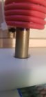
- Before winding the 3mm copper tube on the mandrel I slipped a heat shrink tube over it so that the final product would have insulation between turns. After wrapping, gently shrink the tubing so that air pockets can escape, prevent trapped air bulging, before using on the induction board. Rather than join the coil to the larger copper pipe I sleeved the copper pipe at the points where it connects to the board, ie solder an outer copper sleeve around the thinner coil. This allowed the coil pipe flowing the coolant to extend past the board and not risk leaks onto it….though maybe the longer piping is contributing to my higher no-load current draw through some eddy current effect.

- Admittedly I didn’t read every post before setting out on my build. I wish I had read the post recommending fitting the pump high to aid in removing air bubbles naturally. Anyway, rocking and rolling the unit eventually bled the air.

- Initially I used a 12V 70A truck relay to switch the 48V supply to the heater thinking the massively over-rated current allowance would allow for the higher voltage. The relay lasted 10 cycles before smoke came out. A 40A unit I had at hand lasted 1 cycle, possibly opening the relay and bending the contact arms as others described would have prevented them getting fried. The induction board is, not surprisingly, highly inductive so contact tips work hard. I have some 60V schotyky diodes on order and will trial those across the board as freewheeler to see if that reduces voltage spikes.

- The next replacement relay was a solid state SSR-100 DD (100A 3-32V DC control switching 5-60V) sitting on a bed of heat compound bolted to aluminium angle bar. After 100 no load cycles the home-made heat sink was uncomfortably hot though probably wouldn’t have ever failed as they are designed to get pretty warm. The slow postal delivery of the heat sink (first one went missing in the mail) prompted me to go out and buy and fit a standard 240V AC coil relay consistent with Gina’s design. The simple solution is working perfectly (SY4044 Jaycar model).

- The only changes I made to Gina’s design was to add some indicators and a trapdoor option. Indicators for 240V, 12V, 48V supplies…not really necessary because the timer powers up with 240V and the voltmeter shows 48V but the 12V system indicator is handy. The other change was to add a small impeller flow indicator from Amazon to the cooling system so that I can see that the coolant is flowing, I will fit a small Perspex window in the top to be able to check it periodically; they seem to be sensitive to orientation, mine only wants to spin in the horizontal position, be wary of trapping air bubbles in the impeller so orientate to allow them to pass. Maybe friction on the spline overcomes the gentle flow (3mm pipe is very restrictive) when not horizontal. The trapdoor has a pushbutton so that I can activate it, this is handy to immediately drop a case out, also handy to check it is working before adding the first piece of brass and test the 12V supply is on. With that option you don’t really need a 12V indicator as a working solenoid indicates 12v available.

- 20200423_080911.jpg 20200423_080722.jpg The build has been a great project to work on and very enjoyable so thanks again to Gina. I’m already planning the next mod or maybe new build using a DPS5020 panel that will precisely and easily control the current limit.
 
Heat shrink YES !! great idea. I do see one problem in your build. The metal bracket under your coil, may be pulling parasitic current from your coil. Normal no load current is usually 8.6 amps.
Gina
 
I'm going to have to try the shrink wrap on my unit
I also like how you wire tied the coils together

Dang! Heat shrink was a good idea!
For coil insulation I used this product: https://www.wirecare.com/category/s...nsultherm-ultra-flex-8-awg-natural-10-ft-cuts
...it works but does add additional spacing between the coils. The heat shrink could allow for a tighter winding...

As an aside, I'm trying to gauge if a desire or need for a thread index/catalog exists... Could ease the process of getting information and highlight our members' builds... Let me know ;)
 
Last edited:
Heat shrink YES !! great idea. I do see one problem in your build. The metal bracket under your coil, may be pulling parasitic current from your coil. Normal no load current is usually 8.6 amps.
Gina
Hi Gina, i tested the current moving the bracket away and then into the position shown, the current only increased by 0.1A due to parasitic effect, for such a minimal impact I didnt pursue a non conducting material.
 
OK, that's good. I was wondering do you ever raise our platform so it's closer to the coil ? For example I shoot 6mm dasher. For my neck and shoulders for the case to be in the coil, the coil is almost touching the the platform. Hence in this case it would be closer the the metal bracket.
 
OK, that's good. I was wondering do you ever raise our platform so it's closer to the coil ? For example I shoot 6mm dasher. For my neck and shoulders for the case to be in the coil, the coil is almost touching the the platform. Hence in this case it would be closer the the metal bracket.

I only reload 243, I was reloading also 223 but the std factory ammo in the Lithgow Arms 102 was so good, and not that expensive for my occassional use, decided to just focus on 243. I presently have metal packers above the bracket underneath the box (ie between l-bar and bix underside) that drops the corian plate 2 or 3mm. These photos show how far into the coil it sits. Any suggestions or comparisons welcomed.
 

Attachments

  • 20200424_145257.jpg
    20200424_145257.jpg
    63.5 KB · Views: 80
  • 20200424_145239.jpg
    20200424_145239.jpg
    70.1 KB · Views: 77
Here in Australia we have 240VAC, and if you make a mistake working with that it is often fatal. For that reason I have designed my annealer to run on 48VDC and 12VDC. I have attached below my wiring diagram, which has only taken me about two years to get around to drawing. Mine is auto feed, and is controlled by a case from the auto feed roller passing a proximity sensor as it drops into a funnel and then into the coil. The prox sensor is energised and activates the timer. The timer closes the relay and holds it closed for the set duration (e.g. 5.8 secs). The next timer opens the trapdoor for 0.4 sec and drops the case. Everything then waits for the next case to drop past the prox sensor and start the process again. Hope this is of some assistance to those working with 240VAC.

HI Bruce, are you using the std Sestos quad timer? What relay did you use to switch power to the board? The resistors with the arrows and text should be referring to 48V probably.
 
@Andrew1101 - your case positioning looks fine. You could even go a touch deeper, I'd think. If 400 degree Tempilaq only melts 1/5 of the way down the case, I think you're completely fine there, too.

Clean looking design! And great though on the heat shrink tube!
 
HI Bruce, are you using the std Sestos quad timer? What relay did you use to switch power to the board? The resistors with the arrows and text should be referring to 48V probably.
Well spotted Andrew - yes, the resistors are for 48V.

My timer is " PTR4-SP Controller 4-Way Programmable Time Relay 99 step multi-channel " from EBay for about $50. The buttons are beneath the screen (in the black area of the photo) and are a bit small and fiddly but they work. As I have said before, I got this timer because I was not certain that the Sestos timer would accept an input signal from my proximity sensor to start the process. I now believe that it does.

s-l500.jpg


The relay is " Heavy Duty Chassis Mount Relay " - 30A - $7.95 from Jaycar

upload_2020-4-25_12-53-46.png
Both have worked flawlessly for over 6,000 rounds now.
 

Attachments

  • upload_2020-4-25_12-52-12.png
    upload_2020-4-25_12-52-12.png
    9.1 KB · Views: 8
Just wanted to drop in and post a thanks to Gina and Hollywood.
So thanks to you both.
Only joined this forum specifically for access to this thread, but have found much more useful info.
Finished my annealer today, it is more or less identical to the base model.
Just had to substitute some 240v stuff in as I am in Australia.
Goes like a champ, 3.6 seconds for 223, the rest of my calibres will have to wait till I get to shoot some off.

Regards
Geoff.
 
@Andrew1101 - your case positioning looks fine. You could even go a touch deeper, I'd think. If 400 degree Tempilaq only melts 1/5 of the way down the case, I think you're completely fine there, too.

Clean looking design! And great though on the heat shrink tube!
Well spotted Andrew - yes, the resistors are for 48V.

My timer is " PTR4-SP Controller 4-Way Programmable Time Relay 99 step multi-channel " from EBay for about $50. The buttons are beneath the screen (in the black area of the photo) and are a bit small and fiddly but they work. As I have said before, I got this timer because I was not certain that the Sestos timer would accept an input signal from my proximity sensor to start the process. I now believe that it does.

s-l500.jpg


The relay is " Heavy Duty Chassis Mount Relay " - 30A - $7.95 from Jaycar

View attachment 1174257
Both have worked flawlessly for over 6,000 rounds now.
Well spotted Andrew - yes, the resistors are for 48V.

My timer is " PTR4-SP Controller 4-Way Programmable Time Relay 99 step multi-channel " from EBay for about $50. The buttons are beneath the screen (in the black area of the photo) and are a bit small and fiddly but they work. As I have said before, I got this timer because I was not certain that the Sestos timer would accept an input signal from my proximity sensor to start the process. I now believe that it does.

s-l500.jpg


The relay is " Heavy Duty Chassis Mount Relay " - 30A - $7.95 from Jaycar

View attachment 1174257
Both have worked flawlessly for over 6,000 rounds now.[/QUOTE

That is handy to know, the sentos timer was a long lead time, and yours is a true quad relay timer whereas sentos only has 2 outputs. Also good to know about that 12v relay, after no success with the truck starter type I went for the jaycar version of that in 240v version. When the dps5020 arrives i will rewire the front panel, remove the 3 power lights and might take out the 240v coil then; like yourself I avoid the 240V circuits where ever possible.
 

Upgrades & Donations

This Forum's expenses are primarily paid by member contributions. You can upgrade your Forum membership in seconds. Gold and Silver members get unlimited FREE classifieds for one year. Gold members can upload custom avatars.


Click Upgrade Membership Button ABOVE to get Gold or Silver Status.

You can also donate any amount, large or small, with the button below. Include your Forum Name in the PayPal Notes field.


To DONATE by CHECK, or make a recurring donation, CLICK HERE to learn how.

Forum statistics

Threads
165,802
Messages
2,203,312
Members
79,110
Latest member
miles813
Back
Top