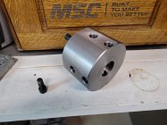
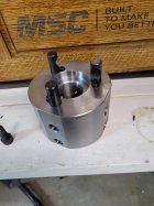
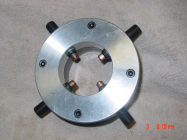
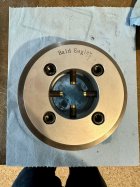
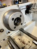
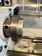
Although I do not have a lathe, I follow all chambering related posts with great interest, and have for some time. I believe that I first saw this setup in a post by Alex wheeler. Since then I suggested what seems to me to be an improvement (that a friend has built and likes) that would not be visible in a picture like this. In order to make setup with a barrel easier. The inboard tips of the screws are first cut with cones in which the bearing balls sit, then they are drilled for a slip fit of small, strong rod magnets that are epoxied in place so that they just clear the balls, so that they do not interfere with their fit in the cone recesses.Very clever Mr. BoydAllen!
You are using an out of date browser. It may not display this or other websites correctly.
You should upgrade or use an alternative browser.
You should upgrade or use an alternative browser.
Spiders Rule, 4-Jaws Drool
- Thread starter INTJ
- Start date
ridgeway
Silver $$ Contributor
LVLAaron
Gold $$ Contributor
I believe that this version solves the issue of barrel movement caused by heavy cuts.
I'd like to build something like this but I want to have the "jaws" retained in the fixture somehow.
butchlambert
Site $$ Sponsor
Nez, Bamban, on this forum has used this method for quite some time.I believe that this version solves the issue of barrel movement caused by heavy cuts.
butchlambert
Site $$ Sponsor
xr650rRider
Silver $$ Contributor
Copper also creeps, just when you thought you had it dialed in.
butchlambert
Site $$ Sponsor
Haven't had that problem in many years. Brass can slip!Copper also creeps, just when you thought you had it dialed in.
Lucky Shooter
Gold $$ Contributor
I made an inboard spider by doing my best to copy the internal
MT-5 taper and using the typical brass-tipped screws.
This seemed to work for me and I did a few barrels with it before
allowing it to live at Ackleyman's place. He modified it a bit and has
used it some.
This might be a good project for some of you who are real machinists.
A. Weldy
MT-5 taper and using the typical brass-tipped screws.
This seemed to work for me and I did a few barrels with it before
allowing it to live at Ackleyman's place. He modified it a bit and has
used it some.
This might be a good project for some of you who are real machinists.
A. Weldy
i have a self made outboard with 4 screws, and i made an inboard also with 4 screws.
the inboard allows work on shorter blanks, and
for really short i have a fitted extention that goes inside the outborard to effectively shorten the distance to the inboard..
the inboard allows work on shorter blanks, and
for really short i have a fitted extention that goes inside the outborard to effectively shorten the distance to the inboard..
Dusty Stevens
Shiner
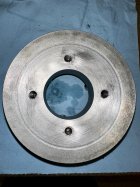
You ought to face that chuck adapter off as far as you can so you can make the spider even closer to the spindleGot the inboard spider finished. Came out okay. There was interference with one camloc lock screw. At that point I could only drill about 1/2", maybe a little more. It was perfect for a 1" allen bolt. All the rest were drilled an inch deep and I used 1.25" long allen bolts.View attachment 1401169View attachment 1401176View attachment 1401177View attachment 1401178
That adapter is big enough to be the spider!!You ought to face that chuck adapter off as far as you can so you can make the spider even closer to the spindle
Dusty Stevens
Shiner
I have seen them turned way down and used as a spider before bald eagle started selling themThat adapter is big enough to be the spider!!
You ought to face that chuck adapter off as far as you can so you can make the spider even closer to the spindle
It can't be as long as I use the Grizzly Gunsmith Spider, or any other, that has four mounting holes. The four mounting holes in the spider don't play well with the three camlocs in the chuck plate. Like I mentioned, one of my spider mounting holes is directly behind a camloc lock screw. That leaves me 1/2" to drill and maybe 3/8" of thread engagement on the spider mount opposite that lock screw.
Besides, this is for home, and I don't do no stinkin' short barrels at home. I think I am 19" from outside of spider to outside of spider.
I did just finish chambering a barrel with it works fine.
BuffaloBill
Silver $$ Contributor
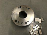
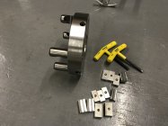
I made this one from a chunk of round stock (eBay) to directly mount against my D1-6 spindle. Made it with only four of the usual six camloc pins, so that the camloc pins and lock screws do not interfere with the four 1/2-20 set screws. I don’t have a CNC mill, just used the DRO to locate positions for pins & lock screws, and used a cheap rotary table to fixture it locate, drill & tap the set screws. Thankfully the camloc pins fit the spindle nicely.
I’d found a camloc dimensional print pdf online which gave me the hardware locations and spindle nose taper & dimensions, drawing it in CAD in order to obtain X/Y coordinates.
Made a few sets of blocks to accommodate shank and muzzle ends of barrels. i used 1/4” bearing balls. Permanent marker numbers get wiped off during dialing. I should stamp numbers in it someday. A nephew has a laser marking machine; could ask him to do that for me.
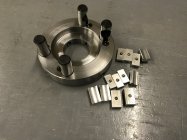


Not following- why do you need the screws numbered?Permanent marker numbers get wiped off during dialing. I should stamp numbers in it someday. A nephew has a laser marking machine; could ask him to do that for me.
BuffaloBill
Silver $$ Contributor
I like some reference to keep track of which pair I’m dialing towards zero. As I rotate the spindle, I can easily loose track of the position I was working on. If a person were careful enough, no mark would be necessary I suppose.Not following- why do you need the screws numbered?
Similar threads
- Replies
- 2
- Views
- 355
- Replies
- 101
- Views
- 4,038
Upgrades & Donations
This Forum's expenses are primarily paid by member contributions. You can upgrade your Forum membership in seconds. Gold and Silver members get unlimited FREE classifieds for one year. Gold members can upload custom avatars.

Click Upgrade Membership Button ABOVE to get Gold or Silver Status.
You can also donate any amount, large or small, with the button below. Include your Forum Name in the PayPal Notes field.
To DONATE by CHECK, or make a recurring donation, CLICK HERE to learn how.

Click Upgrade Membership Button ABOVE to get Gold or Silver Status.
You can also donate any amount, large or small, with the button below. Include your Forum Name in the PayPal Notes field.
To DONATE by CHECK, or make a recurring donation, CLICK HERE to learn how.


