• This Forum is for adults 18 years of age or over. By continuing to use this Forum you are confirming that you are 18 or older. No content shall be viewed by any person under 18 in California.

Open Trickler: The DIY Smart Powder Trickler

I would love to have a kit available that I could connect to my vibrating trickler. I am not electronics savvy enough. I tried to program one of those Arduino's for a small project I was playing with and never could get it to work.
I found an early (7-8yrs old) video where Adam had a solution to do just this. Presume it was the predecessor to the autotrickler. I e-mailed him asking if he still offers something like this and that there's likely a bunch of us folks with capable scales but just need a way to do this at a much lower cost than the current autotrickler. I got my FX 120i for the precision and that if I ever wanted to move up to an autotrickler or supertrickler I'd already had a compatible scale. However since I don't do competition I just can't see myself spending that much on top of the scale. I'm pretty sure i could do the open trickler project successfully, but might take a while and more frustration than I want. I could spend that time with my fingers on the trickler.
 
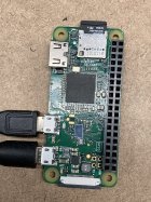
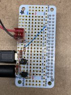
It’s been a while since I did this and messed with the software but this is a picture of the Pi board and the board to add custom circuitry.
Not much to it. A couple transistors, resistors, diode and connectors.
I’ll see if I can find the schematic for what I did. I think the upper board is clled a proto bonnet.
 

Attachments

  • 0C93BE16-13CD-4152-BAC9-73F5C46D18B9.jpeg
    0C93BE16-13CD-4152-BAC9-73F5C46D18B9.jpeg
    761.9 KB · Views: 18
  • EA211543-36ED-4359-926B-92C185747D24.jpeg
    EA211543-36ED-4359-926B-92C185747D24.jpeg
    605 KB · Views: 19
Last edited:
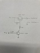
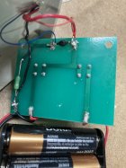
This is what I did on the proto bonnet. I also added a diode in the Dandy control to suppress any motor spikes (the black device). The other device looks like a pico fuse. Can’t remember if I added it or if it was already there.

Edit: The 3 volts shown on the schematic comes from the Pi. I chose to use the batteries in the Dandy controller to be able to use the buttons also. The diode on the schematic isolates the Pi from the Dandy power. Not totally sure I needed it, but just in case. I don’t use the buttons at the same time the Pi is running (the motor).
 

Attachments

  • 4F45DC9B-3BD2-454B-971C-3588DD330D53.jpeg
    4F45DC9B-3BD2-454B-971C-3588DD330D53.jpeg
    338.9 KB · Views: 19
  • AFC4B5AC-66F2-47C3-B7E5-CD9F73F7C7E3.jpeg
    AFC4B5AC-66F2-47C3-B7E5-CD9F73F7C7E3.jpeg
    359.1 KB · Views: 19
Last edited:

Upgrades & Donations

This Forum's expenses are primarily paid by member contributions. You can upgrade your Forum membership in seconds. Gold and Silver members get unlimited FREE classifieds for one year. Gold members can upload custom avatars.


Click Upgrade Membership Button ABOVE to get Gold or Silver Status.

You can also donate any amount, large or small, with the button below. Include your Forum Name in the PayPal Notes field.


To DONATE by CHECK, or make a recurring donation, CLICK HERE to learn how.

Forum statistics

Threads
165,794
Messages
2,203,503
Members
79,128
Latest member
Dgel
Back
Top