Follow along with the video below to see how to install our site as a web app on your home screen.
Note: This feature may not be available in some browsers.
This Forum is for adults 18 years of age or over. By continuing to use this Forum you are confirming that you are 18 or older. No content shall be viewed by any person under 18 in California.
I'm doing this for school project. First I model a Remington 700 bolt and processed to start modifying to make sure it would be right. This is .308 bolt
1st I pulled the prints off PTG and Badger sites (PTG uses a 45 degree off set, Badger uses 30 degrees)
For the bushing I'm going to use .625 OD which is stated for magnum. But since there is no measurement called out for .308 or .223 I'm left to use this one. Or go with a slightly smaller bushing like .500 OD
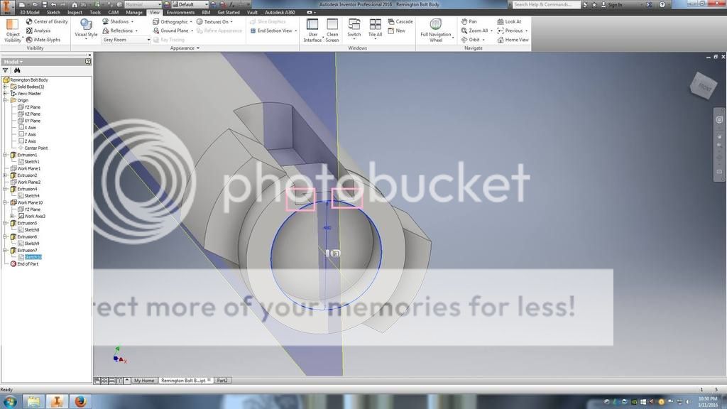
The issue is the cut of .115 doesn't appear to be deep enough.
Here is to show my reference point (OD of the bolt) and depth is correct per the drawing. The bolt body is .696 OD and the bolt nose is (lugs forward to bolt nose) is 0.693OD. I'm measuring the bolt I have off my factory rifle.
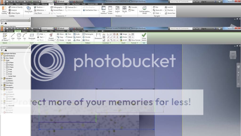
It seems the correct way is to mill the slot deeper, but how deep? In the model I could use guess and check to find it would take .145 cut to get completely through bolt body to rid the area in pink squares above.
Don't know if this helps, but I just installed m16 extractors on 4 remington magnum bolts and the .115 dimension was correct. Maybe contact Badger and see what they have to say. Just a thought.
Don't know if this helps, but I just installed m16 extractors on 4 remington magnum bolts and the .115 dimension was correct. Maybe contact Badger and see what they have to say. Just a thought.
I believe you are correct. Just don't have the info to prove it. I would imagine somebody else will chime in and set us straight. Lol.Good luck with your project.
I'll go all the way back to a sentence I read that was written years ago, by Frank DeHass; "If you have the part in hand it will tell you what size 'hole' it will fit correctly into, conversely, if you don't have the part but have the "hole", measuring the hole will tell you what size the part should be". Not trying to be crude, rude or unreasonable, here, but you have the part. All the solid modeling programs in the world are not a substitue for on site measurement and deductive reasoning.
I'll go all the way back to a sentence I read that was written years ago, by Frank DeHass; "If you have the part in hand it will tell you what size 'hole' it will fit correctly into, conversely, if you don't have the part but have the "hole", measuring the hole will tell you what size the part should be". Not trying to be crude, rude or unreasonable, here, but you have the part. All the solid modeling programs in the world are not a substitue for on site measurement and deductive reasoning.
While I have the part and CAD model is exact copy of my part in hand. The print and the instructions aren't clear. Last think I want to do it cut to deep (ruin the bolt). Magnum and lapua are easily wrote out and .115 works. Standard, assumably, is for 308 bolt face of .475
It's not other than I've never done this before (extractor install). As I said it's for project for school. For this project we have to model the part, generate/edit g-code and setup go and make any fixtures we need. If this was a mag. bolt I wouldn't be here, there's documented installs.
What hes trying to say is you have the part in your hand- measure it. While we can appreciate you having to do all that good stuff to learn (very good to see) it seems you cant see the forest for the trees (so to speak).
I don't have the extractor to measure just the bolt. Thought about modeling up a 308 case (at least the head) to get a better idea.
I admit I'm stuck on the .115 number but appears to only work for mag bolts.
Doing some digging a mag face is 0.536 and standard is .475. Difference of .061. Half that is 0.0305. I had to add almost .030 to the initial .115 to get through the bolt on the .308. I could be on to something or its just luck that the numbers are really closely matching up.
Badger list 3 different p/n for the extractors each # corresponds to a different case head dia. Is it possible that the depth of cut is the same for all 3 P/N s and that the part itself compensates for the difference in case head dia.? If this was the case you could drop the tool down to clear out the matl in the pink boxes after the groove was cut for the ext. If the tool left a small radius on the soldered in ring in the corners where it meets the bolt face it wouldnt really interfere with anything. I only have the ext. for the lapua mag or I would measure and confirm. Hope my rambling is clear
I've worked many, many times from nothing but a print,,,,, that's how industry communicates. If I had doubts or questions, I'd contacted the company that sent me the print that they wanted their part(s) made to. CALL BADGER! Just what type of 'schooling' are you engaged in?
I just did one yesterday on a Borden bolt, the cut was .140" deep. But its for a drop port and I do not want any pressure from the extractor on the case head.
I don't have the extractor to measure just the bolt. Thought about modeling up a 308 case (at least the head) to get a better idea.
I admit I'm stuck on the .115 number but appears to only work for mag bolts.
Doing some digging a mag face is 0.536 and standard is .475. Difference of .061. Half that is 0.0305. I had to add almost .030 to the initial .115 to get through the bolt on the .308. I could be on to something or its just luck that the numbers are really closely matching up.
For a student practicing the use of CAD, this is actually a good exercise. Without the extractor actual dimensions, you really can't finish it. I can only speak for PTG Mini-M16 extractors with bolts machined by PTG and they definitely move the depth of the entire pocket toward the center. Once you have the extractor modeled you can easily shift it to the best location relative to the bolt.
Tomorrow is Monday. A couple of phone calls should get the information you need.
I've change my mind and going to a Mini. I have a defiance but it looks to be different than Badger in one small area. I'll have to call PTG to get a extractor print. I have model the extractor using my Defiance but I'm finding the dimension on the badger printer (hole location for one) is not working so I had to modify that.
I'm a drafter by trade so to make it "harder" I started to use Inventor with HSM Pro to learn a new system. Starting to like it better than Creo, which is what I use on a daily bases.
The extractor is by far hard to get the front edge angles so I'm doing a lot of "just get it look how I think it functions"
Thoughts? on the engagement? I'm thinking the casing floats in the extractor a bit to give clearance and only contacts the case when the bolt is pulled back during extraction, correct?
This Forum's expenses are primarily paid by member contributions. You can upgrade your Forum membership in seconds. Gold and Silver members get unlimited FREE classifieds for one year. Gold members can upload custom avatars.
This site uses cookies to help personalise content, tailor your experience and to keep you logged in if you register.
By continuing to use this site, you are consenting to our use of cookies.