Quick Question on bullet smoothness.
How smooth does the bullet need to be? My initial reaction is that it should be as smooth as possible but two things make me doubt that. First is that the bullet is "scratched up" by the rifling as it leaves the barrel. This is used in forensics to match the bullet to the gun. The second is that BRL did a study way back when that estimated only 5% of bullet drag is due to air drag. The rest is due to the shock wave (wave drag) and the base drag (recirculation of the air behind the bullet).
I'm asking because I'm turning solid copper bullets now and I need to know what standard I should aim for with the surface finish. The smoother the finish, the longer it takes and the more they will cost. SMAAI doesn't have any standards I can find.
AerospikeBullets.com
Shoot them and see if there is an accurracy difference at 100 yards. Maybe farther.
Shoot them and see if there is an accurracy difference at 100 yards. Maybe farther.
I've literally shot thousands of these while developing them and not seeing any difference in accuracy. I mostly shoot out to 60 yards for maximum radar accuracy but even at 100 yards I don't see a difference. I guess my question is what would you want to see as far as surface finish?
It may sound counterintuitive but very smooth might not be the best option. I remember seeing something about racing yachts being faster with a slightly rougher surface like shark skin. Air may behave differently to water of course.
I've literally shot thousands of these while developing them and not seeing any difference in accuracy. I mostly shoot out to 60 yards for maximum radar accuracy but even at 100 yards I don't see a difference. I guess my question is what would you want to see as far as surface finish?
My guess is that the most important thing would be how square the base is to the centerline of the bullet and consistant pointing. Your machined bases and points are probably better than swaged. Riflng groves on the bullet probably swamp any affect from bullets smoothness. You don't have all the variables involved in swaging bullets, jacket quality, lead quality, lead weight, the amount of pressure applies at each swagging step and so on.
It may sound counterintuitive but very smooth might not be the best option. I remember seeing something about racing yachts being faster with a slightly rougher surface like shark skin. Air may behave differently to water of course.
The principle is the same. The reason golf ball have dimples is because they fly further. Race boats don't wax the bottom becaise it creats drag and slows the boat down.
Does the golf ball fly truer or the boat goes straighter, I don't know.
I know that airplane wings sometimes have trip wires that intentionally break up the smooth surface to create turbulent flow. The aerospike base is designed to minimize turbulence to reduce drag so maybe smoother is better for them.
The principle is the same. The reason golf ball have dimples is because they fly further. Race boats don't wax the bottom becaise it creats drag and slows the boat down.
Does the golf ball fly truer or the boat goes straighter, I don't know.
With dimples they go twice as far. 200 fps vs 3000 fps bullet. Gulf ball no shock wave.
In another post you displayed some radar data and it showed measurements out to 50 or 60 yards your post above mentioned shooting out to 60 yards for radar. Are you estimates of drag C_d and ballistic coefficients for your bullets made using the radar data from the first 60 yards of the trajectory?
I ask because the signal to noise of your measurements is much lower than it could be, if only including data from the first 60 yards. The drop in the first 60 yards is a small fraction of the total drop of the bullet over ranges that it might be employed. Since you are claiming low drag I would assume that your target customer is the long range shooter so assume the range of interest is 1,000 yards.
Please explain how you are measuring/estimating the ballistic coefficient of your bullets.
Where is the popcorn, here we go again! Lol
Paul
I know that airplane wings sometimes have trip wires that intentionally break up the smooth surface to create turbulent flow. The aerospike base is designed to minimize turbulence to reduce drag so maybe smoother is better for them.
Trip wires? Can you please show me a picture? I've never seen one.
In another post you displayed some radar data and it showed measurements out to 50 or 60 yards your post above mentioned shooting out to 60 yards for radar. Are you estimates of drag C_d and ballistic coefficients for your bullets made using the radar data from the first 60 yards of the trajectory?
I ask because the signal to noise of your measurements is much lower than it could be, if only including data from the first 60 yards. The drop in the first 60 yards is a small fraction of the total drop of the bullet over ranges that it might be employed. Since you are claiming low drag I would assume that your target customer is the long range shooter so assume the range of interest is 1,000 yards.
Please explain how you are measuring/estimating the ballistic coefficient of your bullets.
Great question!
I'm using what is commonly called the Mann Barrel method. For each round of testing I will make a lot of bullets and load them in the case with reduced powder to get the desired Mach number. I'll then shoot a sample (10-25) of each powder load and collect the velocity data out to the range of the radar.
Hint: With the reduced powder method, small fill % below about 50% causes misfires. We fill the case with a filler to prevent this. This is not a common technique and not recommended for the general shooter as it can create pressure spikes and damage your gun or hurt you!
By looking at the radar spread, the grouping, and the yaw cards I can measure the average Mach number of the test lot and the drag coefficient. The yaw card and spread of the data confirm stability. When I worked with the Navy I also had access to high speed cameras but they are out of my price range right now. Like the data I posted showed, you could clearly see the bullet start to go unstable below Mach 2.2.
To get lower Mach data for the same bullet, you have to switch to a faster twist to re-stabilize it.
Most testing ranges have a set of barrels with various twist for a fixed mount gun called a Mann Gun that makes this test easier. I have to switch between cartridges to get the data.
For example, I started my 30 caliber design on the .308 Win and wasted years trying to prove aerospikes but the 1:10 twist is too slow. When I fire the same bullet out of a 300 Blackout with a 1:8 twist I get great data. I'm currently looking at getting a 300 PRC with a 1:8 twist that I can use to collect the high Mach data for that bullet.
Some calibers are easy. The 5.56 can easily be found in twist from 1:10 to 1:7.
There is sooo many things wrong in this thread!
I think you answered your own question, with your comment about shooting thousands of them in various surface condition and saw no real difference.
Just a decent looking surface would seem fine too me.
A “rough” surface texture aids creating a boundary layer of air around the bullet or any object for that matter and improves the aerodynamic properties. Slick polished surfaces are “stickier” rough and create more drag in fluid dynamics. Examples of this are things like boat hulls, golf balls and cylinder head ports. No polished surfaces create less drag once objects are set into motion.
I was hoping for a picture of one on an actual airplane wing in service. Theoretical drawings from a text book are one thing. Implementation is something different.
Show me a picture of a trip wire (not a lap joint in the skin or improperly filled butt joint) on the wing of a western-built aircraft that produces lower drag or better boundary-layer conditions.
This paper applies specifically to low Reynolds Number airfoils and little to nothing related to surface roughness. While some wings may have turbulent inducing flow devices that are designed to break up a laminar boundary layer to create a turbulent boundary layer and delay the onset of separation to increase lift and to reduce drag. This is a classic example used to reduce the drag of a non rotating sphere by putting a wire perpendicular to the direction of flow.
Surface roughness is not going to be a large component of in supersonic and transonic flows. Pressure and wave drag predominate. At subsonic flows the surface roughness over a body does become a major component of drag.
I was hoping for a picture of one on an actual airplane wing in service. Theoretical drawings from a text book are one thing. Implementation is something different.
Show me a picture of a trip wire (not a lap joint in the skin or improperly filled butt joint) on the wing of a western-built aircraft that produces lower drag or better boundary-layer conditions.
Keith,
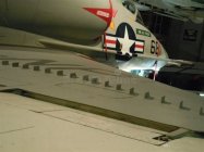
A-4 Skyhawk. Not a wire but vortex inducing "device".
-
vortex generator.jpeg
21.3 KB
· Views: 39
Not a wire but vortex inducing "device".
Aero socks. Yes they are a real thing.


This paper applies specifically to low Reynolds Number airfoils and little to nothing related to surface roughness. While some wings may have turbulent inducing flow devices that are designed to break up a laminar boundary layer to create a turbulent boundary layer and delay the onset of separation to increase lift and to reduce drag. This is a classic example used to reduce the drag of a non rotating sphere by putting a wire perpendicular to the direction of flow.
Surface roughness is not going to be a large component of in supersonic and transonic flows. Pressure and wave drag predominate. At subsonic flows the surface roughness over a body does become a major component of drag.
Keith,
A-4 Skyhawk. Not a wire but vortex inducing "device".
It might be kinda hard to put vortex generators on a bullet but good friend had them installed on his Bonanza with a nice reduction in stall speed and about a 100lb increase in useful load.


