itchyTF
Gold $$ Contributor
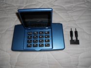
Checking the electronics in the M2 main unit.
I seem to be happiest when I have projects to do (electronic, mechanical or electro-mechanical). A couple of years ago I was designing a PC board for a couple of other projects and decided to include a circuit to check the CED M2 electronics (not the sensors). The intention was just to see if the M2 would read correctly across its range. So, I made a little device that plugs into the sensor’s jacks and gets its power from the M2’s battery. The device has a pushbutton that when pushed, outputs a start/stop signal for 7 different ranges. The eighth push will start the sequence over again. Velocities after the first push will generate an OR error (Out of Range) on the M2 – “The velocity being shown is not within plus/minus 7% of the current average velocity.â€
The following may be too detailed for some but I have a point at the bottom.
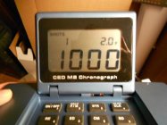
Because of the microcontroller and crystal I chose, the resolution ended up about 1 microsecond (μs). My intention was to shoot for the following speeds - 1,000, 2,000, 3,000, 4,000, 5,000, 6,000 and something less than 7,000 which is the limit of the M2. Because of the resolution limit, I ended up with 1,000, 2,000, 3003, 4,000, 5,000/1, 6,006/8 and 6,970/2. Getting an even thousand was not important, having the M2 read the signal correctly was. To get exactly 3,000 fps the signals would have to be 666.66 μs apart. Because of my 1 μs resolution I ended up with virtually 666 μs. I say virtually because the oscilloscope I used to measure it came up with 665.96 and 665.98 μs. The 5,000/1 issue could be tolerances with my device, the M2 and/or rounding. But that is only a .02% error. The time difference between 5,000 and 5,001 is only about 80 nanoseconds. I believe the 6,006/8 is the same type of thing. I would need 333.33 μs to get 6,000 even. According to the scope, I ended up with 332.98 and 332.99 μs. These numbers yield 6,006.4 and 6,006.2 respectively. So, the 6,006 is a good number. The 6,008 is probably due to the same issues mentioned above. But it is only a .03% error. Since the M2 won’t respond to anything above 7,000 (mine at least), I had to go less. I originally had a signal that was giving me 6,993 which was 286 μs but was only 326 nanoseconds away from not giving a reading so I increased it 1 μs to be safe. That should have yielded 6,969 but I was getting 6,970/2. Again, probably due to tolerances and/or rounding and, worst case, that is only a .04% error. However, I don’t think anyone is exercising the M2 too much above 4,000 fps.
I originally had 10 of the circuit boards made but when I looked for them recently I could only find 8 (plus the one I originally made). For whatever reason I decided to finish the remaining 8. There are only 9 components on the board. Six of them are surface mount requiring a microscope to solder them (at least for my eyes). The little sucker is labor intensive and don’t plan on making any more. I would like to try to sell the 8 extras for a very reasonable price and will list the ad in the Tools section of the For Sale area. It’s relatively inexpensive (I’m really not making any money on them) and would give eight M2 owners peace of mind that their device is working correctly (or not!).
For sale link - http://forum.accurateshooter.com/index.php?topic=3831051.new#new

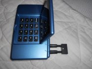
There are 6 components on this side.

I seem to be happiest when I have projects to do (electronic, mechanical or electro-mechanical). A couple of years ago I was designing a PC board for a couple of other projects and decided to include a circuit to check the CED M2 electronics (not the sensors). The intention was just to see if the M2 would read correctly across its range. So, I made a little device that plugs into the sensor’s jacks and gets its power from the M2’s battery. The device has a pushbutton that when pushed, outputs a start/stop signal for 7 different ranges. The eighth push will start the sequence over again. Velocities after the first push will generate an OR error (Out of Range) on the M2 – “The velocity being shown is not within plus/minus 7% of the current average velocity.â€
The following may be too detailed for some but I have a point at the bottom.
Because of the microcontroller and crystal I chose, the resolution ended up about 1 microsecond (μs). My intention was to shoot for the following speeds - 1,000, 2,000, 3,000, 4,000, 5,000, 6,000 and something less than 7,000 which is the limit of the M2. Because of the resolution limit, I ended up with 1,000, 2,000, 3003, 4,000, 5,000/1, 6,006/8 and 6,970/2. Getting an even thousand was not important, having the M2 read the signal correctly was. To get exactly 3,000 fps the signals would have to be 666.66 μs apart. Because of my 1 μs resolution I ended up with virtually 666 μs. I say virtually because the oscilloscope I used to measure it came up with 665.96 and 665.98 μs. The 5,000/1 issue could be tolerances with my device, the M2 and/or rounding. But that is only a .02% error. The time difference between 5,000 and 5,001 is only about 80 nanoseconds. I believe the 6,006/8 is the same type of thing. I would need 333.33 μs to get 6,000 even. According to the scope, I ended up with 332.98 and 332.99 μs. These numbers yield 6,006.4 and 6,006.2 respectively. So, the 6,006 is a good number. The 6,008 is probably due to the same issues mentioned above. But it is only a .03% error. Since the M2 won’t respond to anything above 7,000 (mine at least), I had to go less. I originally had a signal that was giving me 6,993 which was 286 μs but was only 326 nanoseconds away from not giving a reading so I increased it 1 μs to be safe. That should have yielded 6,969 but I was getting 6,970/2. Again, probably due to tolerances and/or rounding and, worst case, that is only a .04% error. However, I don’t think anyone is exercising the M2 too much above 4,000 fps.
I originally had 10 of the circuit boards made but when I looked for them recently I could only find 8 (plus the one I originally made). For whatever reason I decided to finish the remaining 8. There are only 9 components on the board. Six of them are surface mount requiring a microscope to solder them (at least for my eyes). The little sucker is labor intensive and don’t plan on making any more. I would like to try to sell the 8 extras for a very reasonable price and will list the ad in the Tools section of the For Sale area. It’s relatively inexpensive (I’m really not making any money on them) and would give eight M2 owners peace of mind that their device is working correctly (or not!).
For sale link - http://forum.accurateshooter.com/index.php?topic=3831051.new#new
There are 6 components on this side.