TL;DR: How do you take into consideration ports on the top of the brake and baffles not on the same plane as the horizontal baffles?
I got around to reading a book a bought a while ago called "Armament Engineering, a computer aided approach" by H Peter. I found the chapter on muzzle brakes really fascinating, however they neglected to cover asymmetric muzzle brake design. On small arms, asymmetrical brakes are the most common, since those ports on the top help to reduce muzzle climb. I have tried looking around for any documents on this subject and found the "Engineering Design Handbook, Gun Series, Muzzle Brakes" by the US Army Material Command and they do mention about asymmetrical muzzle brakes, but I am having trouble understanding what is going on. Their terminology isn't identical to the armament engineering book and they don't break down the equations and seem to have overly complicated ones. Also the asymmetric muzzle brake they describe is really strange, instead of it being a common brake where it has large side ports and a small port on top, it is a funky brake the has the sides hooking up at a specified angle. So I don't think that document will be of much help.
I also have some questions about the calculations and considerations to muzzle brakes. Lets use the one in the image below as a common example one.

Lets say we want to calculate the downward force from having the top right port. Is that considered a separate port? Or do we take that area and combine it with port series 1? Where exactly does it fall into the equations, because port series 2 (the middle side ports) takes values computed from series 1 to yield its' results and since that top port is also redirecting gases, that should effect series 2. Then what about the next vertical port, would it follow the equations relative to series 2 ports and on? But say we used the equations listed in the armament engineering book, we can only compute thrust on the baffle, while what we need is the thrust from the gas flow exiting the port. I am tempted to think they are equal, but the force on the baffle is a force towards the user (i.e. recoil mitigating) while the thrust force from the vertical port is, well vertically downward.
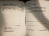
Attached below are the important pages from the armament engineering book so you can see what the equations I am dealing with are. Sorry for the reduced image quality, but the server refuses to upload the images without them being reduced by over 75%...


There are two other images but the forum is glitching saying I can only attach 6 files...when I have only 4, I will add them into a comment if possible.
Any help you can offer in figuring out the hand calculations of these is much appreciated!
I got around to reading a book a bought a while ago called "Armament Engineering, a computer aided approach" by H Peter. I found the chapter on muzzle brakes really fascinating, however they neglected to cover asymmetric muzzle brake design. On small arms, asymmetrical brakes are the most common, since those ports on the top help to reduce muzzle climb. I have tried looking around for any documents on this subject and found the "Engineering Design Handbook, Gun Series, Muzzle Brakes" by the US Army Material Command and they do mention about asymmetrical muzzle brakes, but I am having trouble understanding what is going on. Their terminology isn't identical to the armament engineering book and they don't break down the equations and seem to have overly complicated ones. Also the asymmetric muzzle brake they describe is really strange, instead of it being a common brake where it has large side ports and a small port on top, it is a funky brake the has the sides hooking up at a specified angle. So I don't think that document will be of much help.
I also have some questions about the calculations and considerations to muzzle brakes. Lets use the one in the image below as a common example one.
Lets say we want to calculate the downward force from having the top right port. Is that considered a separate port? Or do we take that area and combine it with port series 1? Where exactly does it fall into the equations, because port series 2 (the middle side ports) takes values computed from series 1 to yield its' results and since that top port is also redirecting gases, that should effect series 2. Then what about the next vertical port, would it follow the equations relative to series 2 ports and on? But say we used the equations listed in the armament engineering book, we can only compute thrust on the baffle, while what we need is the thrust from the gas flow exiting the port. I am tempted to think they are equal, but the force on the baffle is a force towards the user (i.e. recoil mitigating) while the thrust force from the vertical port is, well vertically downward.
Attached below are the important pages from the armament engineering book so you can see what the equations I am dealing with are. Sorry for the reduced image quality, but the server refuses to upload the images without them being reduced by over 75%...
There are two other images but the forum is glitching saying I can only attach 6 files...when I have only 4, I will add them into a comment if possible.
Any help you can offer in figuring out the hand calculations of these is much appreciated!