After reading the detailed and insightful thread posted here by Lee Martin on bullet making, I was encouraged to start a thread on my current .264" jacket making project. I've always been keen to swage my own bullets but the biggest barrier in my way was sourcing jackets here in Australia. It was during a Covid lockdown last year that I decided to give jacket making a red hot go.
Step 1: Research
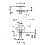
I began researching the deep drawing process and anything related to bullet jacket manufacture. A lot of the information was for high volume mass production especially large press tooling. I needed to gather all of this up and shrink the whole thing down to a small, manual benchtop process. I settled on C12200 0.7mm (.027") copper sheet which can ordered fully annealed. Deep drawing of copper is based around a basic set of rules. The first cup draw has a maximum limiting drawing ratio (LDR) of 2:1. The cup punch diameter is no less than half of the blank disc diameter. The subsequent drawing stages then have an approximately 22% reduction ratio. Lengthening each draw requires "ironing" and I settled on a 17% ironing ratio to form a 1.4" long final jacket. This is controlled by the punch diameter. A larger punch diameter increases the ratio.
The calculated forces needed were about 1.13 ton for blanking and under 0.25 ton for the drawing operations. To reduce the required force of blanking, I designed the punch with a slight 1.5 degree angle face. This "shear angle" reduced the force down to 0.2 ton.
Step 2: The Press
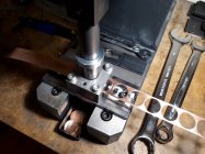
I ordered a 2 ton arbor press online and set it up on a work bench in my spare bedroom. The reason for using an arbor press and not a large compound lever press was simple. The force needed for deep drawing is constant through the whole stroke not at the end of the stroke like an O frame press. The quality was average for a Chinese made press but would be just fine for my prototype tooling. The plan was to make "proof of concept" dies and punches and see if it works.
Step 3: Prototype tooling
My background is in consumer product design and I've worked in manufacturing for over 30 years. My main tool of the trade is CAD so everything was drawn up digitally so prototype parts could be CNC machined straight off my files. The dies looked like big versions of Redding neck sizing bushes. These inserts then dropped in an off the shelf shaft guide block. Punches were made by ordering HSS drill rod blanks and grinding an end radius. The dies were CNC machined by a prototyping bureau in 1018 mild steel. Stripper plates and die mounting plates were cut from scrap steel. So far nothing fancy.
-
Prototype Tooling 01.jpg
194.2 KB
· Views: 146
-
Prototype Tooling 02.jpg
115.3 KB
· Views: 147
Step 3: Prototype Tooling continued
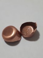
The very first cup that formed completely was a relief. Previous attempts (without annealed blanks) were an absolute disaster and I was quickly learning about how the material flowed between the punch and die. The cup die was redesigned with a refined internal profile and another version machined. Because the punches are straight walled there is also enormous "grabbing" of the cup to the punch and the mild steel stripper fork was straining as I was raising the punch. The new die profile worked very well. So well that it is the same profile used in the later final hardened dies. At this stage I had not ordered any dial indicators or micrometers. I spent most of my career working to no less than 0.05mm (0.002"). Now I was try to work out how accurate were my first cups. The answer....not very. I made up some jigs to test TIR and concentricity. The punch was not centered, not even close. Not to be deterred, I continued with the other drawing dies. I was finally getting a fully formed .261" jacket albeit with major concentricity error. Happy so far but with lots of work ahead
Pic of very first drawn cup on original die......big fail
-
First Attempt Cup.jpeg
69.4 KB
· Views: 34
Step 4: Evaluation
I started thinking about all the things that worked and didn't work. The list for "didn't work" was quite long not surprising. Basically the die holder and the punch holder could not be aligned or maintain alignment.
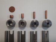
The first additional part I designed was a calibration die. This die has a "v" tapered hole like a morse taper. The punch when pushed into the taper can find true center then the die plate is locked in place. This simple step made a huge difference. The next design change was to ensure the die found true center into the die plate. All of the dies were re-designed with a screw in thread and a tapered shoulder. As the die is tightened, it aligns itself with a corresponding taper in the die plate. Now I felt confident that the next iteration would yield results. These dies were machined in 4140 and through hardened and then nitrided to 60 HRC. They were all machined undersized as I was going to lap the internal surfaces.
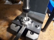
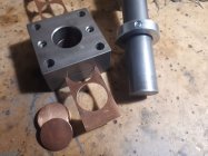
Pics of the new final draw die design and die holder. The photo shows the second form die from cup to .40" jacket
-
Forming Die 01.JPG
37.6 KB
· Views: 109
-
MK2 die and holder.jpg
235.4 KB
· Views: 108
Step 5: Measurement
I have made a couple of small batches with the latest tooling and have now got a better picture of the quality and accuracy. My dial indicator reads in 0.01mm increments so concentricity measurements should be taken as indicative. First batches were within 0.02mm (0.0008"). I looked at a few changes to the arbor press. It now has brass gib screws and the punch holder uses an ER collet with a custom machined collet holder. I found using lubricant sparingly has additional gains. I am now using straight castor oil. I am also testing a 4:1 mix of castor oil and acetone. The jackets have a super thin coating once the acetone has evaporated.
Last batches run consistently around 0.01mm (0.0004"). The pinch die slightly deforms the jacket around the edge so its best to measure the jacket untrimmed. I have now put on hold making any more jackets until my swaging dies arrive. Hopefully I will have some great test results to share once I have a finished batch of bullets. The goal is to make a match quality .264" 130 grain FB bullet to shoot through my favorite 6.5x55 rifle. The idea of making a quality bullet from start to finish seemed a bit of a dream but I think I can see it all coming together. Stay tuned for part 2
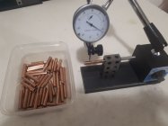
Pics of the dial indicator concentricity gage and jacket final diameter
-
Jacket test 02.jpg
147.9 KB
· Views: 93
-
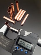
Trimmed .261 jacket.jpg
240.9 KB
· Views: 94
This is excellent! Thank you so much for sharing. I don't have anything to add but want to share my enthusiasm for your results! I will eagerly await your updates.
Your results are nothing short of amazing, considering you do not have a mentor! This is no small feat by any means. Looking forward to your next post. Best of luck.
Paul
Find yourself a small Alva Allen press. I had one in the
shop I wish I never sold. We used it to form copper
side plugs for preadjusted carburetors. They looked
like gas checks for 25 caliber bullets.
Thanks Evan and Paul for your kind words. I hope to add a few more updates soon. Thanks Fuj, I had a look at images of the Alva Allen Press. It would be nice to automate the process with a small flywheel press however I'm only looking to make batches of a couple of hundred at a time. More than enough for my shooting needs
The Alva's are fast little buggers, and perfect for blanking.
Too fast for deep drawing though. You can use a variable
gear to slow them down, but then you lose tonnage in the
stroke....I applaud your efforts. Keeps us posted.
Fantastic post. I have been mulling around the same idea.
Doing a great job there. Am i missing something- you say you got annealed sheet but all i seen was the disc. How are you cutting those?
Major respect for anyone who even attempts this!
Doing a great job there. Am i missing something- you say you got annealed sheet but all i seen was the disc. How are you cutting those?
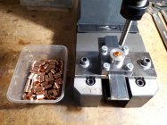
Dusty, I found a copper merchant who can supply sheet annealed and guillotined to size in small quantities. This costs a bit more but suits my requirements perfectly. I organized the sheet (6' x 3') to be cut in strips of 30mm. I also designed a disc punch and die to fit on my die plate and had this machined up in 4140 and through hardened. The punch face has a slight angle (1.5 degrees) to lower the blanking forces on the arbor press. The die is a clamshell design so that each half has a machined recess half the thickness of the strip. When assembled and pinned together with roll pins, it forms a slot for the strip.
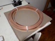
Pics of the punch and die and supplied copper strip
-
Copper Strip 01.jpg
158.2 KB
· Views: 68
-
Disc punch and die 01.jpg
205.4 KB
· Views: 69
-
Disc punch and die 02.jpg
262.5 KB
· Views: 69
Very nice,thanks for sharing!
After reading the detailed and insightful thread posted here by Lee Martin on bullet making, I was encouraged to start a thread on my current .264" jacket making project. I've always been keen to swage my own bullets but the biggest barrier in my way was sourcing jackets here in Australia. It was during a Covid lockdown last year that I decided to give jacket making a red hot go.
Step 1: Research
I began researching the deep drawing process and anything related to bullet jacket manufacture. A lot of the information was for high volume mass production especially large press tooling. I needed to gather all of this up and shrink the whole thing down to a small, manual benchtop process. I settled on C12200 0.7mm (.027") copper sheet which can ordered fully annealed. Deep drawing of copper is based around a basic set of rules. The first cup draw has a maximum limiting drawing ratio (LDR) of 2:1. The cup punch diameter is no less than half of the blank disc diameter. The subsequent drawing stages then have an approximately 22% reduction ratio. Lengthening each draw requires "ironing" and I settled on a 17% ironing ratio to form a 1.4" long final jacket. This is controlled by the punch diameter. A larger punch diameter increases the ratio.
The calculated forces needed were about 1.13 ton for blanking and under 0.25 ton for the drawing operations. To reduce the required force of blanking, I designed the punch with a slight 1.5 degree angle face. This "shear angle" reduced the force down to 0.2 ton.
Step 2: The Press
I ordered a 2 ton arbor press online and set it up on a work bench in my spare bedroom. The reason for using an arbor press and not a large compound lever press was simple. The force needed for deep drawing is constant through the whole stroke not at the end of the stroke like an O frame press. The quality was average for a Chinese made press but would be just fine for my prototype tooling. The plan was to make "proof of concept" dies and punches and see if it works.
Step 3: Prototype tooling
My background is in consumer product design and I've worked in manufacturing for over 30 years. My main tool of the trade is CAD so everything was drawn up digitally so prototype parts could be CNC machined straight off my files. The dies looked like big versions of Redding neck sizing bushes. These inserts then dropped in an off the shelf shaft guide block. Punches were made by ordering HSS drill rod blanks and grinding an end radius. The dies were CNC machined by a prototyping bureau in 1018 mild steel. Stripper plates and die mounting plates were cut from scrap steel. So far nothing fancy.
Do you sell your bullet jackets?
Proauto1@comcast.net
Do you sell your bullet jackets?
Proauto1@comcast.net
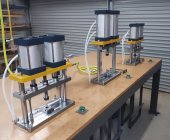
I am currently looking to sell jackets and VLD projectiles in Australia only at the moment. Both USA and Australia require import and export licenses. I will look into this maybe at a later stage but it depends on what calibers and lengths are feasible. Lots of changes since I last posted. I now have designed and built three 1.2 ton pneumatic presses for blanking, drawing, trimming and swaging ops. This allows a capacity of around 15k a month which is fine for my garage setup. Here are a couple of pics and video. More to show soon.
-
20240902_101053.jpg
428.3 KB
· Views: 31
I am currently looking to sell jackets and VLD projectiles in Australia only at the moment. Both USA and Australia require import and export licenses. I will look into this maybe at a later stage but it depends on what calibers and lengths are feasible. Lots of changes since I last posted. I now have designed and built three 1.2 ton pneumatic presses for blanking, drawing, trimming and swaging ops. This allows a capacity of around 15k a month which is fine for my garage setup. Here are a couple of pics and video. More to show soon.
Have you started producing jackets commercially?
Hi Liseo, I'm just concentrating on the 6.5mm projectiles at the moment. Once I have a big enough stockpile I can then start to offer a 1.38" jacket for sale and some other lengths later. I can only offer this in Australia at the moment because of export restrictions.


